


Intel® Server Board SE7520JR2 Design and Environmental Specifications
Revision 1.0
C78844-002
205
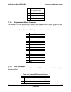
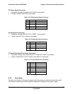
P3 Power Signal Connector
• Connector housing: 5-pin Molex 50-57-9705 or equivalent
• Contacts: Molex 16-02-0087 or equivalent
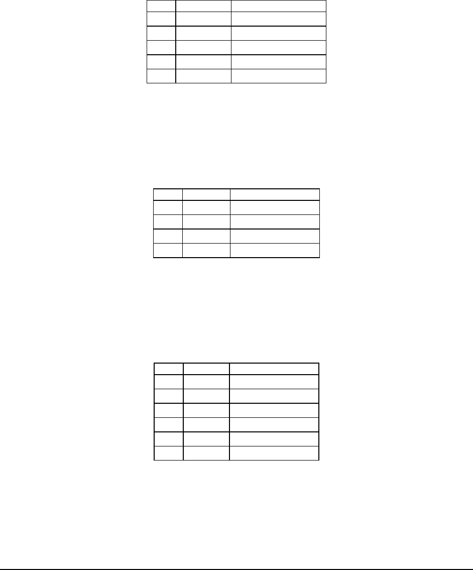
Table 115: P3 Baseboard Signal Connector
Pin SIgnal 24 AWG Color
1 I2C Clock White/Green Stripe
2 I2C Data White/Yellow Stripe
3 Alert# White
4 COM Black
5 3.3RS White/Brown Stripe
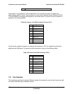
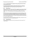
P4 Peripheral Connectors
• Connector housing: AMP V0 P/N is 770827-1 or equivalent
• Contact: Amp 61314-1 contact or equivalent
Table 116: Peripheral Power Connectors
Pin SIgnal 18 AWG Color
1 +12 V3 Yellow/Blue Stripe
2 COM Black
3 COM Black
4 +5 VDC Red
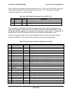
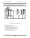
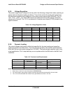
P7 Hard Drive Back Plane Power Connector
• Connector housing: 6-pin Molex Mini-Fit Jr. PN# 39-01-2065 or equivalent
• Contact: Molex Mini-Fit, HCS, female, crimp 44476 or equivalent
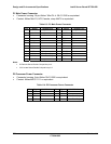
Table 117: P7 Hard Drive Power Connector
Pin Signal 18 AWG Color
1 Ground Black
2 Ground Black
3 5V Red
4 +12V3 Yellow/Blue Stripe
5 +12V3 Yellow/Blue Stripe
6 5VSB Purple
8.2.2 Grounding
The ground of the pins of the power supply output connector provides the power return path.
The output connector ground pins shall be connected to safety ground (power supply