


Intel® Server Board SE7520JR2 Design and Environmental Specifications
Revision 1.0
C78844-002
203
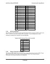
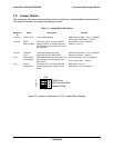
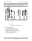
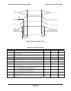
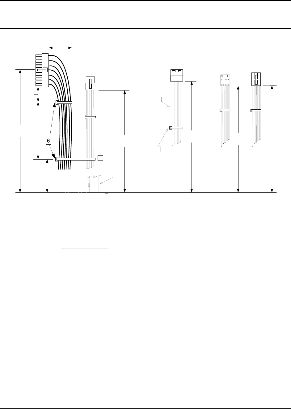
Note: The following diagram shows the power harness spec drawing as defined for use in Intel
server chassis. Reference chassis designs may or may not require all of the connectors shown
and different wiring material may be needed to meet specific platform requirements.
3
P
1
7
5
P
4
210.0
(8.27")
20.0
(0.8")
110 Ref
(4.3")
P
3
P
7
325.0
(12.8")
400.0
(15.7")
240.0
(9.45")
100.0
(3.9")
30.0
(1.2")
P
2
50
(2")
8
Figure 27. Power Harness Specification Drawing
Notes:
1. ALL DIMENSIONS ARE IN MM
2. ALL TOLERANCES ARE +10 MM / -0 MM
3. INSTALL 1 TIE WRAP WITHIN 12MM OF THE PSU CAGE
4. MARK REFERENCE DESIGNATOR ON EACH CONNECTOR
5. TIE WRAP EACH HARNESS AT APPROX. MID POINT
6. TIE WRAP P1 WITH 2 TIES AT APPROXIMATELY 15M SPACING.
7. P4 HARNESS IS ARESERVED FOR THE FUTURE ONLY, NO
8. PLEMENTATION IS NEEDED CURRENTLY.
9. TIE WRAP P1 AND P2 TOGETHER AT THIS POINT.