


Functional Architecture Intel® Server Board SE7520JR2
Revision 1.0
C78844-002
60
• Reduces Interrupt Service Routine (ISR) overhead with interrupt coalescing
• Supports 32-bit or 64-bit data bursts with variable burst lengths
• Supports the PCI Cache Line Size register
• Supports the PCI Memory Write and Invalidate, Memory Read Line, and Memory Read
Multiple commands
• Supports the PCI-X Memory Read Dword, Split Completion, Memory Read Block, and
Memory Write Block commands
• Supports up to 8 PCI-X outstanding split transactions
• Supports Message Signaled Interrupts (MSI)
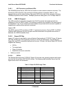
3.4.4.2 Zero Channel RAID
The Server Board SE7520JR2 has support for Zero Channel RAID (ZCR) which follows the
RUBI2 standard. It will not have support for zero channel RAID cards that follow the RADIOS
standard. See the SE7520JR2 Tested Hardware and OS list for a list of supported ZCR cards.
Zero channel RAID (ZCR) capabilities enable the LSI 53C1030 to respond to accesses from a
PCI RAID controller card or chip that is able to generate ZCR cycles. The LSI53C1030’s ZCR
functionality is controlled through the ZCR_EN/ and the IOPD_GNT/ signals. Both of these
signals have internal pull-ups and are active LOW. The ZCR_EN/ signal enables ZCR support
on the LSI53C1030. Pulling ZCR_EN/ LOW enables ZCR operation. When ZCR is enabled, the
LSI53C1030 responds to PCI configuration cycles when the IOPD_GNT/ and IDSEL signal are
asserted. Pulling ZCR_EN/ HIGH disables ZCR support on the LSI53C1030 and causes the
LSI53C1030 to behave as a normal PCI-X to Ultra320 SCSI controller. When ZCR is disabled,
the IOPD_GNT/ signal has no effect on the LSI53C1030 operation. The IOPD_GNT/ pin on the
LSI53C1030 should be connected to the PCI GNT/ signal of the external I/O processor. This
allows the I/O processor to perform PCI configuration cycles to the LSI53C1030 when the I/O
processor is granted the PCI bus. This configuration also prevents the system processor from
accessing the LSI53C1030 PCI configuration registers.
On the Server Board SE7520JR2, a ZCR card is only supported on the full-height riser slot.
When installing the card, it MUST be populated in the PCI-X add-in slot furthest from the
baseboard. No other add-in card slot has support for a ZCR card.
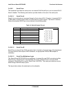
3.4.5 IDE Support
Integrated IDE controllers of the ICH5-R provide two independent IDE channels. Each is
capable of supporting up to two devices. A standard 40-pin IDE connector on the baseboard
interfaces with one channel. The signals of the second IDE channel are routed to the high-
density 100-pin backplane connector for use in either the Intel
®
Server Chassis SR1400 (1U
chassis) or the Intel Server Chassis SR2400 (2U chassis). Both IDE channels can be
configured and enabled or disabled by accessing the BIOS Setup Utility during POST.
The BIOS supports the ATA/ATAPI Specification, version 6. It initializes the embedded IDE
controller in the chipset south-bridge and the IDE devices that are connected to these devices.
The BIOS scans the IDE devices and programs the controller and the devices with their
optimum timings. The IDE disk read/write services that are provided by the BIOS use PIO
mode, but the BIOS will program the necessary Ultra DMA registers in the IDE controller so that
the operating system can use the Ultra DMA Modes.