


Intel® Server Board SE7520JR2 Connectors and Jumper Blocks
Revision 1.0
C78844-002
189
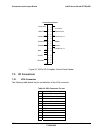
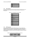
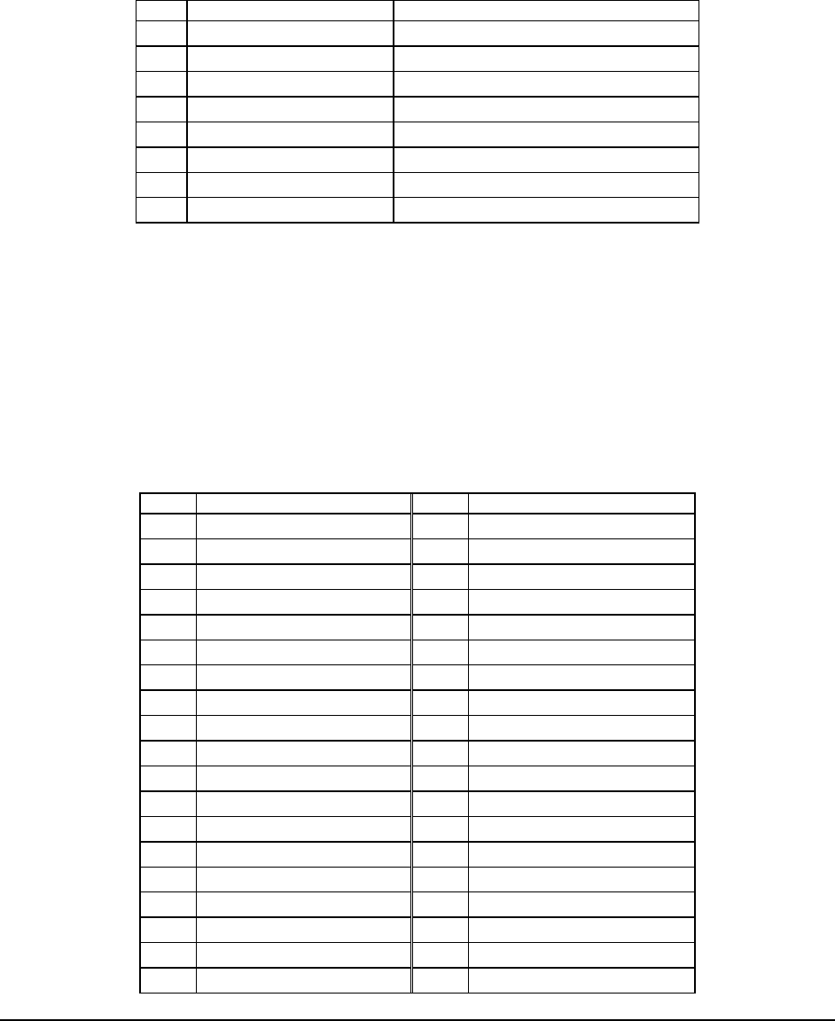
7.3.4 OEM RMC Connector (J3B2)
A white eight pin connector (J3B2) used for OEM specific management cards.
Table 90: OEM RMC Connector Pinout (J3B2)
Pin Signal Name Description
1 PERIPH_I2C_3VSB_SDA
2 PERIPH_I2C_3VSB_SCL
3 POST_STATUS
4 +5V
5 GROUND
6 5V_STBY
7 ICH5_SYS_RST_L
8 FP_PWR_BTN_RMC
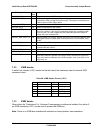
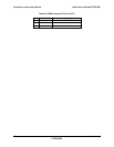
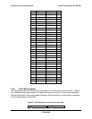
7.4 Control Panel Connectors
The Server Board SE7520JR2 provides three control panel interconnects: a high density 100-
pin connector for use in the Intel Server Chassis SR1400 1U and SR2400 2U with backplane
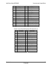
installed, a 50-pin control panel connector used in Intel’s chassis with no backplane installed,
and a SSI standard 34-pin connector for use in third-party reference chassis. The following
tables provide the pinouts for each connector.
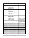
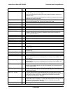
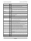
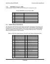
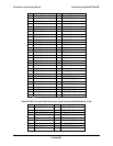
Table 91: 100-Pin Flex Cable Connector Pin-out (For Intel Chassis w/Backplane) (J2J1)
Pin Signal Name Pin Signal Name
A1 GND B1 V_IO_VSYNC_BUFF_FP_L
A2 V_IO_RED_CONN_FP B2 V_IO_HSYNC_BUFF_FP_L
A3 V_IO_GREEN_CONN_FP B3 TEMP_PWM_R
A4 V_IO_BLUE_CONN_FP B4 SPB_DCD_L
A5 VIDEO_IN_USE B5 SPB_CTS_L
A6 SPB_DTR_L B6 SPB_SOUT_L
A7 SPB_RTS _L B7 SPB_EN_L
A8 SPB_SIN B8 LAN_ACT_B_L
A9 SPB_DSR B9 LAN_LINKB_R
A10 FP_NMI_BTN_L B10 FP_CHASSIS_INTRU
A11 GND B11 PS_I2C_5VSB_SCL
A12 FP_ID_BTN_L B12 PS_I2C_5VSB_SDA
A13 P5V_STBY B13 LAN_ACT_A_L
A14 FP_RST_BTN_L B14 LAN_LINKA_R
A15 HDD_FAULT_LED_L B15 FP_ID_LED_R
A16 FP_PWR_BTN_L B16 IPMB_I2C_5VSB_SCL
A17 HDD_LED_ACT_L B17 P5V_STBY
A18 P3V3 B18 FP_STATUS_LED2_R
A19 IPMB_I2C_5VSB_SDA B19 FP_STATUS_LED1_R