


Error Reporting and Handling Intel® Server Board SE7520JR2
Revision 1.0
C78844-002
156
6.3.4 Memory Bus Error
The hardware is programmed to generate an SMI on single-bit data errors in the memory array
if ECC memory is installed. The SMI handler records the error and the DIMM location to the
system event log. Double-bit errors in the memory array are mapped to the SMI because the
mBMC cannot determine the location of the bad DIMM. The double-bit errors may have
corrupted the contents of SMRAM. The SMI handler will log the failing DIMM number to the
mBMC if the SMRAM contents are still valid. The ability to isolate the failure down to a single
DIMM may not be available on certain platforms, and/or during early POST.
6.3.5 System Limit Error
The BMC monitors system operational limits. It manages the A/D converter, defining voltage
and temperature limits as well as fan sensors and chassis intrusion. Any sensor values outside
of specified limits are fully handled by the BMC. The BIOS does not generate an SMI to the host
processor for these types of system events.
6.3.6 Processor Failure
The BIOS detects any processor BIST failures and logs the event. The failed processor can be
identified by the first OEM data byte field in the log. For example, if processor 0 fails, the first
OEM data byte will be 0. The BIOS depends upon the BMC to log the watchdog timer reset
event.
If an OS device driver is using the watchdog timer to detect software or hardware failures and
that timer expires, an Asynchronous Reset (ASR) is generated, which is equivalent to a hard
reset. The POST portion of the BIOS can query the BMC for a watchdog reset event as the
system reboots, and then log this event in the SEL.
6.3.7 Boot Event
The BIOS downloads the system date and time to the BMC during POST and logs a boot event.
This record does not indicate an error, and software that parses the event log should treat it as
such.
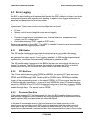
6.4 Error Messages and Error Codes
The BIOS indicates the current testing phase during POST by writing a hex code to I/O location
80h. If errors are encountered, error messages or codes will either be displayed to the video
screen, or if an error has occurred prior to video initialization, errors will be reported through a
series of audio beep codes.
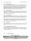
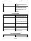
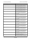
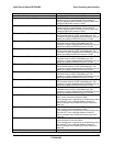
6.4.1 POST Error Messages
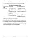
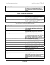
Table 59: Memory BIOS Messages
Message Displayed Description