


Platform Management Intel® Server Board SE7520JR2
Revision 1.0
C78844-002
126
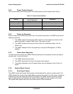
5.3.2 Power Control Sources
The sources listed in the following table can initiate power-up and/or power-down activity.
Table 47: Power Control Initiators
Source
External Signal Name or
Internal Subsystem
Capabilities
Power button Front control power button Turns power on or off
mBMC Watchdog Timer Internal mBMC timer Turns power off or power cycle
Platform Event Filtering PEF Turns power off or power cycle
Command Routed through command processor Turns power on or off, or power cycle
Power state retention Implemented via mBMC internal logic Turns power on when AC power returns
5.3.3 Power-up Sequence
When turning on the system power after one of the event occurrences, the mBMC executes the
following procedure:
1. The mBMC asserts Power Supply (PS) Power On via the chipset and waits for the
power subsystem to assert Power Good. The system is reset.
2. The mBMC initializes all sensors to their Power On initialization states. The Init
Agent is run.
3. The mBMC attempts to boot the system by running the FRB algorithm, if FRB is
enabled.
5.3.4 Power-down Sequence
To power down the system, the mBMC effectively performs the sequence of power-up steps in
reverse order. It occur as follows:
1. The mBMC asserts system reset.
2. The mBMC de-asserts the Power On signal via the chipset.
3. The power subsystem turns off system power upon de-assertion of the Power On
signal.
5.3.5 System Reset Control
5.3.5.1 Reset Signal Output
The mBMC asserts the System Reset signal on the baseboard to perform a system reset. The
mBMC asserts the System Reset signal before powering the system up. After power is stable as
indicated by the power subsystem Power Good signal, the mBMC sets the processor enable
state as appropriate and de-asserts the System Reset signal, taking the system out of reset.
The system reset signal responds to the control panel or IPMI commands.