


Intel® Server Board SE7520JR2 Functional Architecture
Revision 1.0
C78844-002
41
status of the extended memory test is displayed on the console. The status of base and
extended memory tests are also displayed on an LCD control panel if present.
The extended memory test is configured using the BIOS Setup Utility. The coverage of the test
can be configured to one of the following:
• Test every location (Extensive)
• Test one interleave width per kilo-byte of memory (Sparse)
• Test one interleave width per mega-byte of memory (Quick).
The “interleave width” of a memory subsystem is dependent on the chipset configuration. By
default, both the base and extended memory tests are configured to the Disabled setting. The
extended memory test can be aborted by pressing the <Space> key during the test.
3.3.5 Memory Monitoring
Both the baseboard management controller and BIOS provide support for memory inventory,
memory failure LEDs, and failure/state transition events. Memory monitoring features are
supported differently depending on which level of server management is used. The following
table shows how each feature is supported by management level.
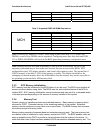
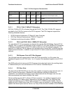
Table 6: Memory Monitoring Support by Server Management Level
Memory Feature On-board Professional Advanced
Inventory No Yes Yes
Correctable Error Reporting No Yes Yes
Uncorrectable Error Reporting Yes Yes Yes
With either Professional or Advanced IMMs installed, the Sahalee BMC maintains one sensor
per DIMM. The sensor is IPMI type 21h, Slot/Connector. The Sahalee BMC directly detects the
presence or absence of each DIMM and records this in offset 2 of these sensors.
DIMM failure can be detected at BIOS POST or during system operation. POST detected DIMM
failures or mis-configuration (incompatible DIMM sizes/speeds/etc) cause the BIOS to disable
the failed/affected DIMMs and generate IPMI SEL events, which are sent to the BMC in use.
In addition, using Professional or Advanced IMMs, the BIOS communicates this failure to the
Sahalee BMC so that it can be incorporated in the BMC’s DIMM sensor state. DIMM presence
and failure states are stored persistently by the Sahalee BMC.
In all management levels, the BIOS is responsible for DIMM FRU LED management and
illuminates the LEDs associated with failed or disabled DIMMs.
Correctable memory errors are non-critical errors that do not cause the system to fail. They are
detected by the BIOS and are logged as IPMI SEL events when either the Professional or
Advanced IMMs are installed. Logging is throttled by error frequency. If more than a certain
number of correctable errors occur in an hour, logging is turned off.