


Platform Management Intel® Server Board SE7520JR2
Revision 1.0
C78844-002
128
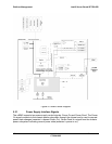
• Combined power and reset button assertion
If DC power is off, an assertion of the PWBTIN while the RSTIN is asserted generates
an OEM-specific Control Panel event to PEF. The event attributes are: Sensor Type
code - 14h (Button) and Sensor Specific offset - 07h. This PEF action initiates a BIOS
CMOS clear request to the system BIOS.
The user interface of the control panel consists of the following indicators:
• Power LED
• Fault/Status LED
• Chassis ID LED
For user input, the standard control panel can provide the following buttons/switches:
• Reset button
• Power button
• NMI/SDI button
• Chassis ID button
• Chassis intrusion switch (optional)
5.3.5.4 Control Panel Indicators
The mBMC is capable of supporting three control panel indicators: Power LED, Fault/Status
LED, and Chassis ID LED. The states of these indicators and how they relate to the
mBMC/chassis state are detailed below.
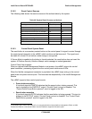
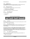
5.3.5.4.1 Power LED
The BIOS controls the control panel Power LED as described in the table below.
Table 49: SSI Power LED Operation
State Power Mode LED Description
Power Off Non-ACPI OFF System power is off, and the BIOS has not initialized the chipset.
Power On Non-ACPI ON System power is on, but the BIOS has not yet initialized the chipset.