


Error Reporting and Handling Intel® Server Board SE7520JR2
Revision 1.0
C78844-002
170
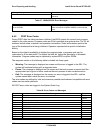
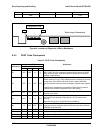
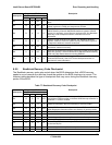
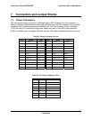
Diagnostic LED Decoder
G=Green, R=Red, A=Amber
Checkpoint
MSB LSB
Description
8C A G OFF OFF Late POST initialization of chipset registers.
8D A G OFF G Build ACPI tables (if ACPI is supported)
8E A G G OFF Program the peripheral parameters. Enable/Disable NMI as selected
90 R OFF OFF R Late POST initialization of system management interrupt.
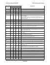
A0 R OFF R OFF Check boot password if installed.
A1 R OFF R G Clean-up work needed before booting to operating system.
A2 R OFF A OFF
Takes care of runtime image preparation for different BIOS modules.
Fill the free area in F000h segment with 0FFh. Initializes the Microsoft
IRQ Routing Table. Prepares the runtime language module. Disables
the system configuration display if needed.
A4 R G R OFF Initialize runtime language module.
A7 R G A G
Displays the system configuration screen if enabled. Initialize the
CPU’s before boot, which includes the programming of the MTRR’s.
A8 A OFF R OFF Prepare CPU for operating system boot including final MTRR values.
A9 A OFF R G Wait for user input at config display if needed.
AA A OFF A OFF
Uninstall POST INT1Ch vector and INT09h vector. Deinitializes the
ADM module.
AB A OFF A G Prepare BBS for Int 19 boot.
AC A G R OFF End of POST initialization of chipset registers.
B1 R OFF R A Save system context for ACPI.
00 OFF OFF OFF OFF Passes control to OS Loader (typically INT19h).
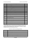
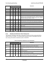
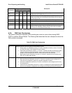
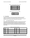
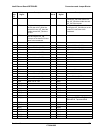
6.5.4 Bootblock Initialization Code Checkpoints
The Bootblock initialization code sets up the chipset, memory and other components before
system memory is available. The following table describes the type of checkpoints that may
occur during the bootblock initialization portion of the BIOS:
Table 76: Bootblock Initialization Code Checkpoints
Diagnostic LED Decoder
G=Green, R=Red, A=Amber
Checkpoint
MSB LSB
Description
Before D1
Early chipset initialization is done. Early super I/O initialization is done
including RTC and keyboard controller. NMI is disabled.
D1 R R OFF A
Perform keyboard controller BAT test. Check if waking up from power
management suspend state. Save power-on CPUID value in scratch
CMOS.
D0 R R OFF R
Go to flat mode with 4GB limit and GA20 enabled. Verify the
bootblock checksum.
D2 R R G R
Disable CACHE before memory detection. Execute full memory sizing
module. Verify that flat mode is enabled.
D3 R R G A
If memory sizing module not executed, start memory refresh and do
memory sizing in Bootblock code. Do additional chipset initialization.
Re-enable CACHE. Verify that flat mode is enabled.