


Intel® Server Board SE7520JR2 Connectors and Jumper Blocks
Revision 1.0
C78844-002
201
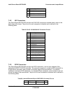
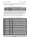
7.8 Jumper Blocks
The baseboard has several jumper blocks used to configure or enable/disable various features.
This section describes the usage and settings of each.
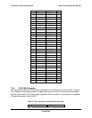
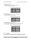
Table 111: Jumper Block Definitions
Reference
ID
Name Description Settings
J1H2 (A) CMOS Clear Clears CMOS settings CMOS Clear by BMC – Pins 1-2 (Default)
CMOS Clear Force Erase – Pins 2-3
J1H2 (B) BIOS
Recovery Boot
Forces the system to boot into BIOS
Recovery mode. A bootable Recovery
BIOS Floppy disk must be in Drive A for
this operation.
Normal Boot - Pins 1-2 (Default)
Enabled – Pins 2-3
J1H2 (C) Password
Clear
Clears Administrator and User
passwords as set in BIOS Setup
Password Clr Protect – Pins 1-2 (Default)
Password Clr Erase – Pins 2-3
J1A4 Rolling BIOS
Configuration
Sets the BIOS flash device to boot from
either the upper or lower banks of the
flash device.
Normal Operation – Pins 1-2 (Default)
Force to lower bank – Pins 2-3
J7A1 Serial B
Configuration
Configures Pin 7 of the RJ45 Serial B
port to support either a DCD or DSR
signal
DCD Select –Pins 1-3
DSR Select – Pins 2-4 (Default)
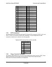
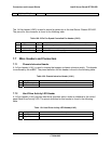
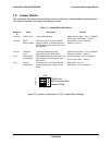
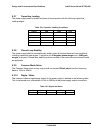
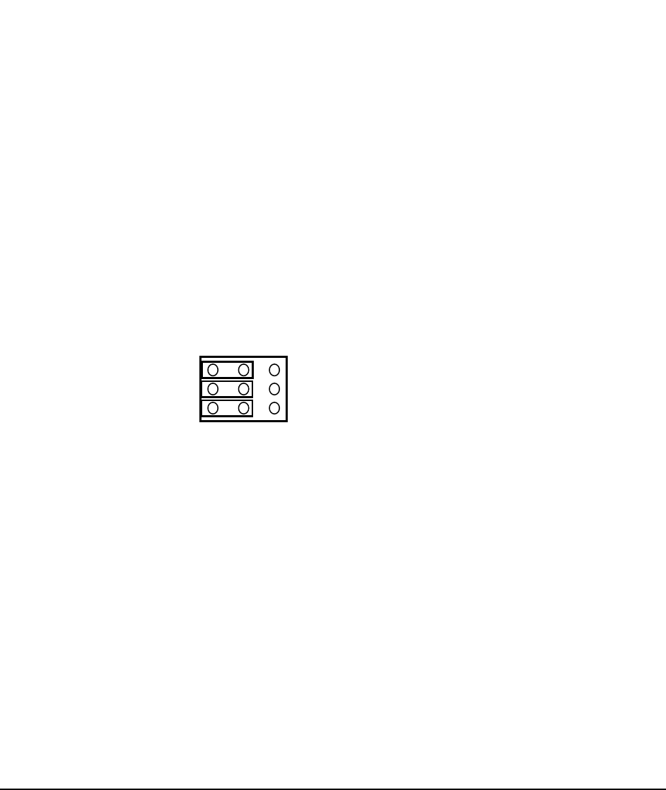
Figure 26. System Configuration (J1H2) Jumper Block Settings
J1H2
B
A
C
1 2 3
CMOS Clear
Password Clear
BIOS Recovery Boot