


Connectors and Jumper Blocks Intel® Server Board SE7520JR2
Revision 1.0
C78844-002
192
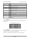
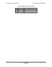
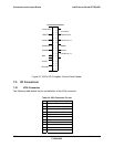
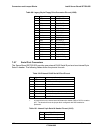
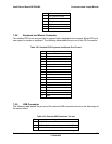
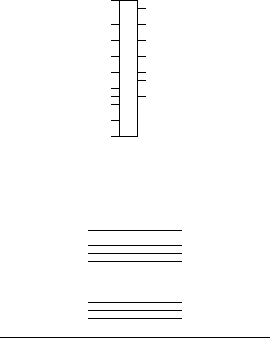
Figure 25. 34-Pin SSI Compliant Control Panel Header
7.5 I/O Connectors
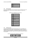
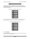
7.5.1 VGA Connector
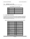
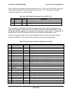
The following table details the pin-out definition of the VGA connector.
Table 94: VGA Connector Pin-out
Pin Signal Name
1 Red (analog color signal R)
2 Green (analog color signal G)
3 Blue (analog color signal B)
4 No connection
5 GND
6 GND
7 GND
8 GND
9 Fused VCC (+5V)
10 GND
11 No connection
O O
O
O O
O O
O O
O O
O O
O O
O O
O O
Intruder
O O
NMI
O O
O O
O O
O O
O O
SMBus
LAN A Link /
A
System Fault
Control Panel Pinout
Sleep Button
ID LED
ID Button
Power LED
Cool Fault
HDD LED
Power Button
Reset Button
LAN B Link /
A