


Functional Architecture Intel® Server Board SE7520JR2
Revision 1.0
C78844-002
54
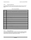
3.4.3.3 Legacy Interrupt Sources
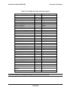
The table below recommends the logical interrupt mapping of interrupt sources on the Server
Board SE7520JR2. The actual interrupt map is defined using configuration registers in the
ICH5-R.
Table 10: Interrupt Definitions
ISA
Interrupt
Description
IRQ0 Timer/counter, HPET #0 in legacy replacement Mode. In APIC mode, cascade from 8259 controller #1
IRQ1 Keyboard
IRQ2 Slave controller INTR output. In APIC mode timer/counter, HPET#0
IRQ3 Serial port A
IRQ4 Serial port B
IRQ5 Parallel Port (Not implemented)
IRQ6 Floppy
IRQ7 Parallel port, generic (Not implemented)
IRQ8 RTC/HPET#1 in legacy replacement mode
IRQ9 Generic, Option for SCI
IRQ10 Generic, Option for SCI
IRQ11 HPET#2, option for SCSI, TCO*
IRQ12 PS2 Mouse
IRQ13 FERR
IRQ14 Primary ATA, legacy mode
IRQ15 Secondary ATA, legacy mode
PIRQA USB 2.0 Controller #1 and #4
PIRQB Video
PIRQC USB 2.0 Controller #3, Native IDE, S-ATA
PIRQD USB 2.0 Controller #2
PIRQE Option for SCI, TCO, HPET#0,1,2
PIRQF Option for SCI, TCO, HPET#0,1,2
PIRQG Option for SCI, TCO, HPET#0,1,2
PIRQH USB 2.0 EHCI controller #1, option for SCI, TCO, HPET#0,1,2
Ser IRQ SIO3
3.4.3.4 Serialized IRQ Support
The Server Board SE7520JR2 supports a serialized interrupt delivery mechanism. Serialized
Interrupt Requests (SERIRQ) consists of a start frame, a minimum of 17 IRQ / data channels,
and a stop frame. Any slave device in quiet mode may initiate the start frame. While in
continuous mode, the start frame is initiated by the host controller.