


Intel® Server Board SE7520JR2 Connectors and Jumper Blocks
Revision 1.0
C78844-002
187
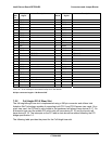
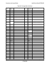
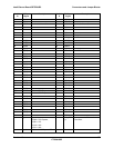
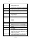
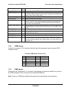
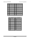
FMC Signal Name FMC
Pin
Description
FMM_RI_BUF_N 97 Ring Indicator from the EMP serial port on the baseboard
RST_PWRGD_PS 101 Power good signal from power subsystem. In typical system, this signal is
connected to PWR_OK signal on power supply. This signal is monitored by the
FMM to detect a Power Supply failure
LAN_SMBALERT_N 102 Alert signal from the motherboard NIC (LOM).
ICH_SLP_S4_N 103 Power Off request from the Chipset
ICH_SMI_BUFF_N 105 SMI signal from Chipset. This signal is monitored by the FMM to detect an “SMI
Time-out” condition. If this signal is asserted for longer than a predefined SMI
Time-out timer, an event is logged and the FMM interrogates the chipset for
further data, such as fatal errors.
CHPSET_ERR_ALERT_N 106 When available from chipset, indicates that a error occurred and FMM will need
interrogate Chipset for further data, such as fatal errors. If not available, leave
as NC.
FP_RST_BTN_N 109 Front panel Reset Button input.
ICH_RST_BTN_N 110 Passthrough of front panel Reset button to the chipset. FMM chassis control
command will also use this.
FP_PWR_BTN_N 113 Front panel power button input.
FMM_IRQ_SMI_N 116 FMM might use this signal to generate an SMI to the system.
FMM_PRES_N 120 When FMM is present, this signal is asserted. This signal can be used to notify
BIOS that a module is present (via routing to GPIO), as well as to control any
logic which behaves differently when FMM is present, such as the FML mux (if
supported), etc
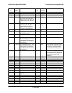
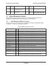
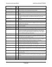
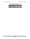
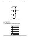
7.3.2 ICMB Header
A white 5-pin header (J1D1) located on the left side of the baseboard near the internal SCSI
connector cutout.
Table 88: ICMB Header Pin-out (J1D1)
Pin Signal Name Type Description
1 5 V standby Power
2 Transmit Signal UART signals
3 Transmit Enable Signal UART signals
4 Receive Signal UART signals
5 Ground GND
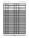
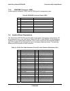
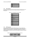
7.3.3 IPMB Header
When either the “Professional” or “Advanced” management modules are installed, the yellow 3-
pin IPMB connector (J3F1) can be used to access the IPMB bus.
Note: There is no IPMB bus available with standard on-board platform instrumentation.