


92 Rabbit 3000 Microprocessor
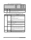
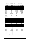
Table 7-10. Real-Time Clock RTCxR Data Registers
Real-Time Clock x Holding Register (RTC0R) R/W (Address = 0x02)
(RTC1R) (Address = 0x03)
(RTC2R) (Address = 0x04)
(RTC3R) (Address = 0x05)
(RTC4R) (Address = 0x06)
(RTC5R) (Address = 0x07)
Bit(s) Value Description
7:0 Read The current value of the 48-bit RTC holding register is returned.
Write
Writing to the RTC0R transfers the current count of the RTC to six holding
registers while the RTC continues counting.
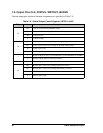
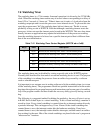
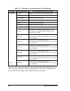
Table 7-11. Real-Time Clock Control Register (RTCCR adr = 0x01)
Bit(s) Value Description
7:0
0x00
Writing a 0x00 to the RTCCR has no effect on the RTC counter.
However, depending on what the previous command was, writing
a 0x00 may either
1. disable the byte increment function or
2. cancel the RTC reset command
If the 0xC0 command is followed by a 0x00 command, only the
byte increment function will be disabled. The RTC reset will still
take place.
0x40
Arm RTC for a reset with code 0x80 or reset and byte increment
function with code 0x0C0.
0x80
Resets all six bytes of the RTC counter to 0x00 if proceeded by
arm command 0x40.
0xC0
Resets all six bytes of the RTC counter to 0x00 and enters byte
increment mode—precede this command with 0x40 arm
command.
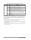
7:6 01
This bit combination must be used with every byte increment write
to increment clock(s) register corresponding to bit(s) set to "1".
Example: 01001101 increments registers: 0, 2,3. The byte
increment mode must be enabled. Storing 0x00 cancels the byte
increment mode.
5:0
0 No effect on the RTC counter.
1 Increment the corresponding byte of the RTC counter.