


204 Rabbit 3000 Microprocessor
• /SLAVEATTN—This line is set low (asserted) if the slave writes to the SPD0R register.
This line is set high if the master writes anything to the slave status register. This line is
usually connected to cause the master to be interrupted when it goes low.
The data lines of the slave port are shared with Parallel Port A that uses the same package
pins. The slave port can be enabled, and Parallel Port A be disabled, by storing an appro-
priate code in the slave port control register (SCR). After the processor is reset, all the pins
belonging to the slave interface are configured as parallel-port inputs unless (SMODE1,
SMODE0) are set to (0,1), in which case the slave port is enabled after reset and the slave
starts the cold-boot sequence using the slave port.
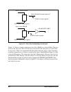
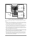
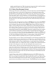
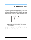
13.1 Hardware Design of Slave Port Interconnection
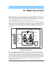
Figure 13-4 shows a typical circuit diagram for connecting two slave Rabbits to a master
Rabbit. The designer has the option of cold-booting the slave and downloading the pro-
gram to RAM on each cold start. Another option is to configure the slave with both RAM
and flash memory. In this case, the slave will only have the program downloaded for
maintenance or upgrades. Usually, the flash would not be written to on every startup
because of the limited number of lifetime writes to flash memory. The slaves’ reset in
Figure 13-4 is under the program control of the master. If the master is reset, the slave will
also be reset because the master’s drive of the reset line will be lost on reset and the pull-
down resistor will pull the slaves’ resets low. This may be undesirable because it forces
the slave to crash if the master crashes and has a watchdog timeout.
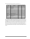
13.2 Slave Port Registers
The slave port registers are listed in Table 13-1. These registers, each of which is actually
two separate registers, one for read and one for write, are accessible to the slave at the I/O
addresses shown in the table and they are accessible to the master at the external address
shown which specifies the value of the slave address (SA0, SA1) input to the slave when
the master reads or writes the registers. The register that can be written by the slave can
only be read by the master and vice versa. If one side were to attempt to read a register at
the same time that the other side attempted to write the register the result of the read could
be scrambled. However, the protocols and handshaking bits used in communication are
normally such that this never happens.
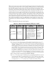
Table 13-1. Slave Port Registers
Register Mnemonic
Internal
Address
External
Address
Slave Port Data 0 Register SPD0R 0x20 0
Slave Port Data 1 Register SPD1R 0x21 1
Slave Port Data 2 Register SPD2R 0x22 2
Slave Port Status Register SPSR 0x23 3
Slave Port Control Register SPCR 0x24 N.A.