


16 Rabbit 3000 Microprocessor
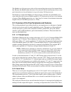
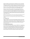
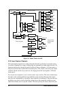
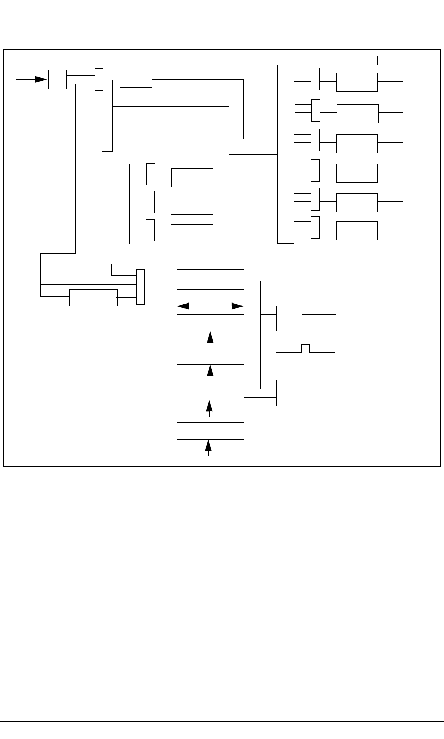
Figure 2-4. Rabbit Timers A and B
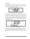
2.2.9 Input Capture Channels
The input capture channels are used to determine the time at which an event takes place.
An event is signaled by a rising or falling edge (or optionally by either edge) on one of 16
input pins that can be selected as input for either of the two channels. A 16 bit counter is
used to record the time at which the event takes place. The counter is driven by the output
of Timer A8 and can be set to count at a rate ranging from full clock speed to 1/256 the
clock speed.
Two events are recognized: a start condition and a stop condition. The start condition may
be used to start counting and the stop condition to stop counting. However the counter
may also run continuously or run until a stop condition is encountered. The start and stop
conditions may also be used to latch the current time at the instant the condition occurs
rather than actually start or stop the counter. The same pin may be used to detect the start
A1
A2
Timer A System
match reg
match reg
compare
Timer B System
match preload
match preload
10 bits
Timer_B1
Timer_B2
A3
A4
A5
A6
A7
perclk
perclk
perclk/2
10-bit counter
A8
Serial E
Serial F
Serial A
Serial B
Serial C
Serial D
Input
Capture
PWM
Quadrature
Decode
A9
A10
Timer A1
perclk/2
perclk/8
Control Timer
Synchronized
outputs