


154 Rabbit 3000 Microprocessor
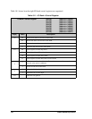
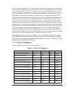
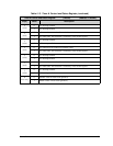
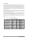
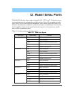
The control register (TACR) is laid out as shown in Table 11-4.
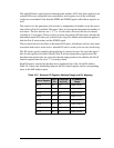
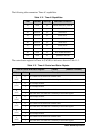
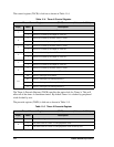
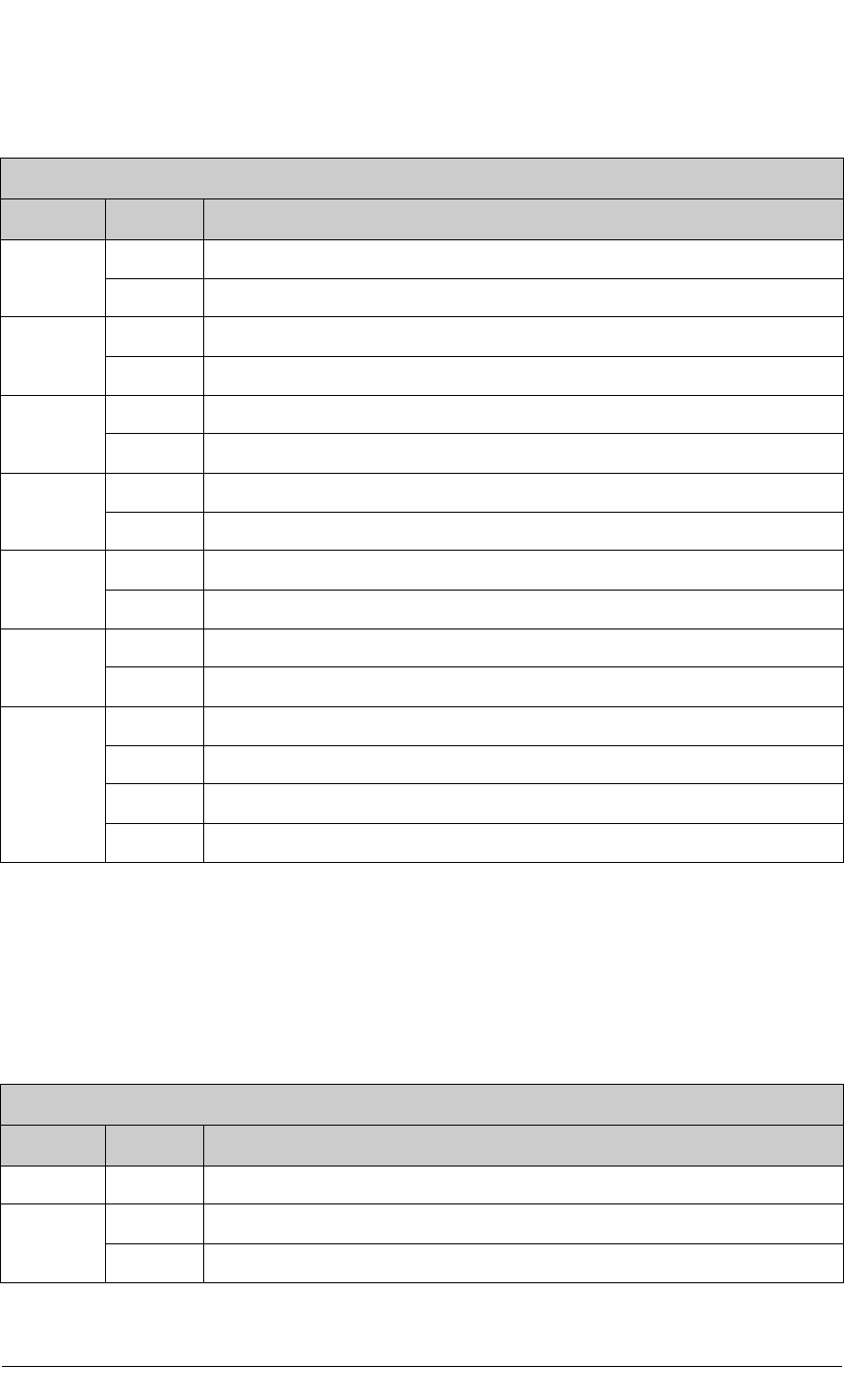
The Timer A Prescale Register (TAPR) specifies the main clock for Timer A. This will
affect all of the timer A countdown timers. By default Timer A is clocked by peripheral
clock divided by two.
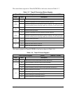
The prescale register (TAPR) is laid out as shown in Table 11-5.
Table 11-4. Timer A Control Register
Timer A Control Register (TACR) (Address = 0x00A4)
Bit(s) Value Description
7
0 Timer A7 clocked by the main Timer A clock.
1 Timer A7 clocked by the output of Timer A1.
6
0 Timer A6 clocked by the main Timer A clock.
1 Timer A6 clocked by the output of Timer A1.
5
0 Timer A5 clocked by the main Timer A clock.
1 Timer A5 clocked by the output of Timer A1.
4
0 Timer A4 clocked by the main Timer A clock.
1 Timer A4 clocked by the output of Timer A1.
3
0 Timer A3 clocked by the main Timer A clock.
1 Timer A3 clocked by the output of Timer A1.
2
0 Timer A2 clocked by the main Timer A clock.
1 Timer A2 clocked by the output of Timer A1.
1:0
00 Timer A interrupts are disabled.
01 Timer A interrupts use Interrupt Priority 1.
10 Timer A interrupts use Interrupt Priority 2.
11 Timer A interrupts use Interrupt Priority 3.
Table 11-5. Timer A Prescale Register
Timer A Prescale Register (TAPR) (Address = 0x00A1)
Bit(s) Value Description
7:1 These bits are ignored.
0
0 The main clock for Timer A is the peripheral clock.
1 The main clock for Timer A is the peripheral clock divided by two.