


User’s Manual 109
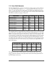
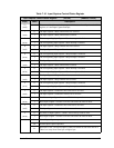
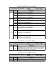
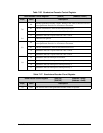
Table 7-22. Input Capture Source x Register
Input Capture Source x Register (ICS1R) (Address = 0x59)
(ICS2R) (Address = 0x5D)
Bit(s) Value Description
7:6 00 Parallel Port C used for Start condition input.
01 Parallel Port D used for Start condition input.
10 Parallel Port F used for Start condition input.
11 Parallel Port G used for Start condition input.
5:4 00 Use port bit 1 for Start condition input.
01 Use port bit 3 for Start condition input.
10 Use port bit 5 for Start condition input.
11 Use port bit 7 for Start condition input.
3:2 00 Parallel Port C used for Stop condition input.
01 Parallel Port D used for Stop condition input.
10 Parallel Port F used for Stop condition input.
11 Parallel Port G used for Stop condition input.
1:0 00 Use port bit 1 for Stop condition input.
01 Use port bit 3 for Stop condition input.
10 Use port bit 5 for Stop condition input.
11 Use port bit 7 for Stop condition input.
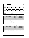
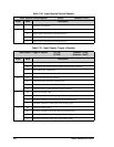
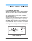
Table 7-23. Input Capture LSB x Register
Input Capture LSB x Register (ICL1R) (Address = 0x5A)
(ICL2R) (Address = 0x5E)
Bit(s) Value Description
7:0 read
The least significant eight bits of the latched Input Capture count are returned.
Reading the lsb of the count latches the msb of the count to avoid reading stale
data. Reading the msb of the count opens the latches.
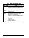
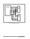
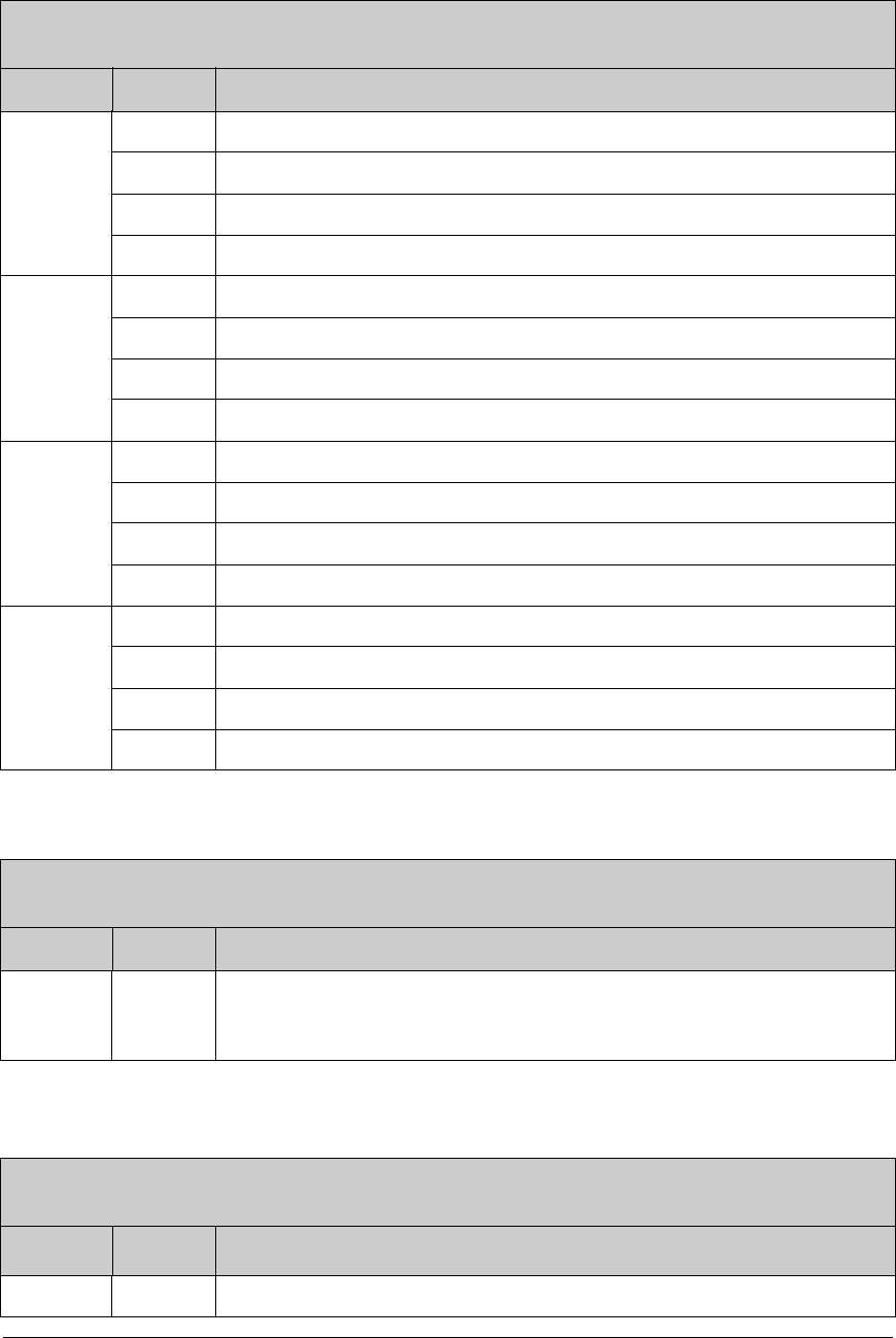
Table 7-24. Input Capture MSB x Register
Input Capture MSB x Register (ICM1R) (Address = 0x5B)
(ICM2R) (Address = 0x5F)
Bit(s) Value Description
7:0 read The most significant eight bits of the latched Input capture count are returned.