


User’s Manual 195
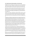
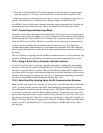
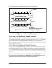
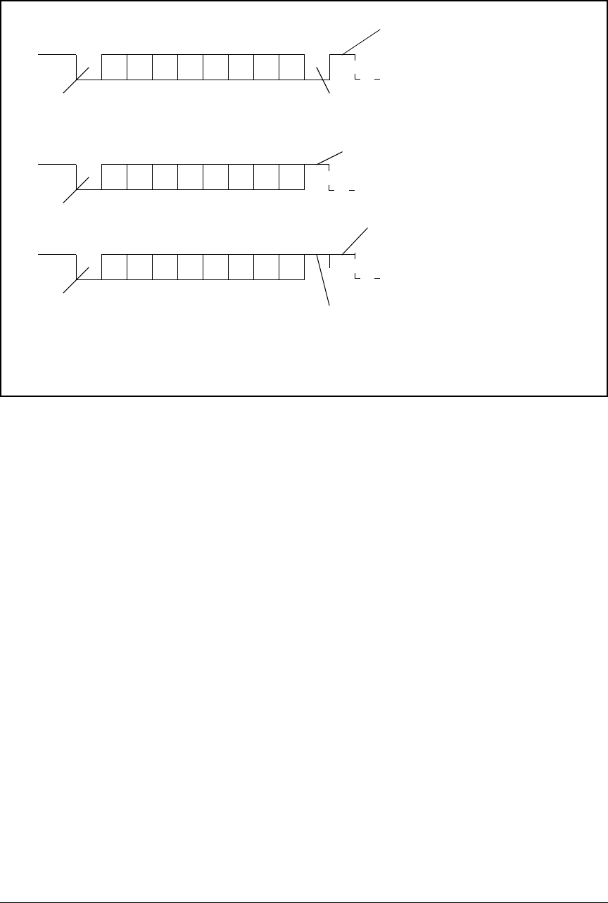
Figure 12-9 illustrates the standard asynchronous serial output patterns.
Figure 12-9. Asynchronous Serial Output Patterns
12.9.6 Parity, Extra Stop Bits with 7-Data-Bit Characters
If only 7 data bits are being sent, sending an additional parity or signal bit is easily solved
by sending 8 bits and always setting bit 7 (the eighth bit) of the byte to "1" or “0” depend-
ing on what is desired. No special precautions are needed if two stop bits are to be
received. If parity is received with 7 data bits, receive the data as 8 bits, and the parity will
be in the high bit of the byte.
12.9.7 Parity, Extra Stop Bits with 8-Data-Bit Characters
In order to receive parity with 8 data bits, a check is made on each character for a 9th bit
low. The 9th bit, or parity bit, is low if bit 6 of the serial port status register (SxSR) is set to
a "1" after the character is received. If the 9th bit is not a zero, then the serial port treats it
as an extra stop bit. So if the 9th bit low flag is not set, it should be assumed that the parity
bit is a "1."
Setting the 9th bit high or low can easily be done in the Rabbit 3000. The 9th bit can be
set low by a write to the Serial Port A-F Address Register (SxAR) and the 9th bit can be
set high by a write to the Serial Port A-F Long Stop Register (SxLR).
start bit
data bits
9th bit low
stop bit
07
07
stop bit
Character with 9th bit low
Character w/o 9th bit low
start bit
Signal shown at output pin on processor. A “1” is high.
start bit
07
stop bit
9th bit high
Character w. 9th bit high
Generated by a Write to SxLR