


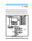
152 Rabbit 3000 Microprocessor
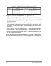
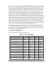
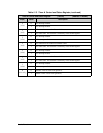
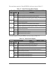
The following table summarizes Timer A’s capabilities.
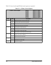
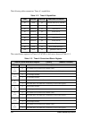
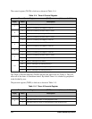
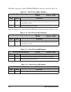
The control/status register for Timer A (TACSR) is laid out as shown in Table 11-3.
Table 11-2. Timer A Capabilities
Timer Cascade
Interrupt Dedicated Connection
A1 none yes Parallel Ports D-G, Timer B
A2 from A1 yes Serial Port E
A3 from A1 yes Serial Port F
A4 from A1 yes Serial Port A
A5 from A1 yes Serial Port B
A6 from A1 yes Serial Port C
A7 from A1 yes Serial Port D
A8 none no Input Capture
A9 none no Pulse Width Modulator
A10 none no Quadrature Decoder
Table 11-3. Timer A Control and Status Register
Timer A Control and Status Register (TACSR) (Address = 0x00A0)
Bit(s) Value Description
7
(read)
0 A7 counter has not reached its terminal count.
1 A7 count done. This status bit is cleared by a read of this register.
7
(write)
0 A7 interrupt disabled.
1 A7 interrupt enabled.
6
(read)
0 A6 counter has not reached its terminal count.
1 A6 count done. This status bit is cleared by a read of this register.
6
(write)
0 A6 interrupt disabled.
1 A6 interrupt enabled.
5
(read)
0 A5 counter has not reached its terminal count.
1 A5 count done. This status bit is cleared by a read of this register.
5
(write)
0 A5 interrupt disabled.
1 A5 interrupt enabled.
4
(read)
0 A4 counter has not reached its terminal count.
1 A4 count done. This status bit is cleared by a read of this register.