


User’s Manual 311
B.1.13 Pulse Width Modulator Improvements
Several new features have been added to the pulse width modulator. First, a new PWM
interrupt can be set up to be requested on every PWM cycle, every other cycle, every
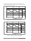
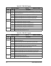
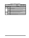
fourth cycle, or every eighth cycle. The setup for this interrupt is done in the PWL0R and
PWL1R registers, listed in Table B-25 and Table B-26.
Options are available to suppress the PWM output for seven-of-eight, three-of-four and
one-of-two iterations of the PWM counter The one-of-eight option works nicely with R/C
servos, which require a 1 ms to 2 ms pulse width and a 20 ms period. This option gives the
full resolution for the pulse width while still meeting the period requirements. The one-of-
four and one-of-two options can be used to create more virtual PWM channels using soft-
ware to multiplex the PWM outputs. There is a separate option to only generate an inter-
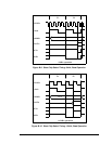
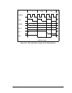
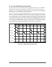
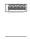
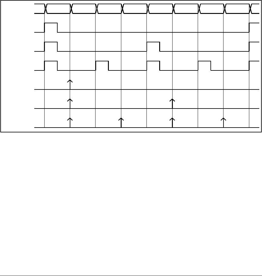
rupt during the active iteration of the PWM count. The timing is shown below.
Figure B-21. PWM Interrupt and Output Timing
iteration
1/4 output
1/8 output
1/2 output
1/8 interrupt
1/4 interrupt
1/2 interrupt
0 1 2 3 4 5 6 7