


User’s Manual 115
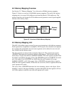
8. MEMORY INTERFACE AND MAPPING
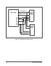
8.1 Interface for Static Memory Chips
Static memory chips generally have address lines, data line, a chip select line, an output
enable line and a write enable. The Rabbit 3000 has these same lines that can connect
directly to a number of static memory chips. The chip selects are not completely inter-
changeable because certain chip selects have special functions. When the processor starts
up, not in cold boot mode, execution starts at address zero in the memory attached to /CS0.
A static RAM should be connected to /CS1 because Dynamic C development tools
assume a static RAM connected to /CS1.
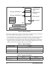
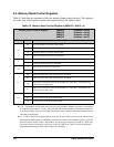
In addition /CS1 has special features that support battery backing of static RAM. When
the processor power is removed but battery power is supplied to the battery power pin
(VBAT) /CS1 is held in a high impedance state. This allows a pull up resistor to the bat-
tery backup power to hold /CS1 high and thus hold the static memory chip in standby
mode. The RESOUT pin is also held high while the processor is powered down and bat-
tery power is supplied to VBAT. This allows the RESOUT pin to be used to control power
to the processor and the static RAM chip via a transistor.
It is also possible to force /CS1 to be enabled at all times. This is convenient if an external
battery backup device is used that might slow down the transition of /CS1 during the
memory cycle. Most users will not use this feature.
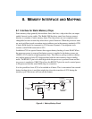
Figure 8-1. Battery-Backup Circuit
Rabbit 3000
RESOUT
3.3 V
Main Power
Rabbit 3000
VBAT
SRAM
VDD
/CS
Rabbit 3000
/CS
100 kW
5 kW
3 V
(p channel)
FDV302P