


156 Rabbit 3000 Microprocessor
11.2 Timer B
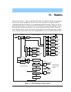
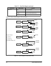
Figure 11-1 shows a block diagram of Timer B. The Timer B counter can be driven
directly by perclk/2, by that clock divided by 8, or by the output of Timer A1. Timer B has
a continuously running 10-bit counter. The counter is compared against two match regis-
ters, the B1 match register and the B2 match register. When the counter transitions to a
value equal to a match register, an internal pulse with a length of 1 peripheral clock is gen-
erated. The match pulse can be used to cause interrupts and/or clock the output registers of
Parallel Ports D and E.
The match registers are loaded from the match preload registers that are written to by an
I/O instruction. The data byte in the match preload register is advanced to the next match
register when the match pulse is generated.
Every time a match condition occurs, the processor sets an internal bit that marks the match
value in TBLxR as invalid. Reading TBCSR clears the interrupt condition. TBLxR must be
reloaded to re-enable the interrupt. TBMxR does not need to be reloaded every time.
If both match registers need to be changed, the most significant byte needs to be changed
first.
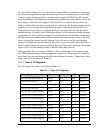
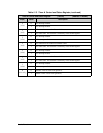
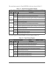
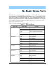
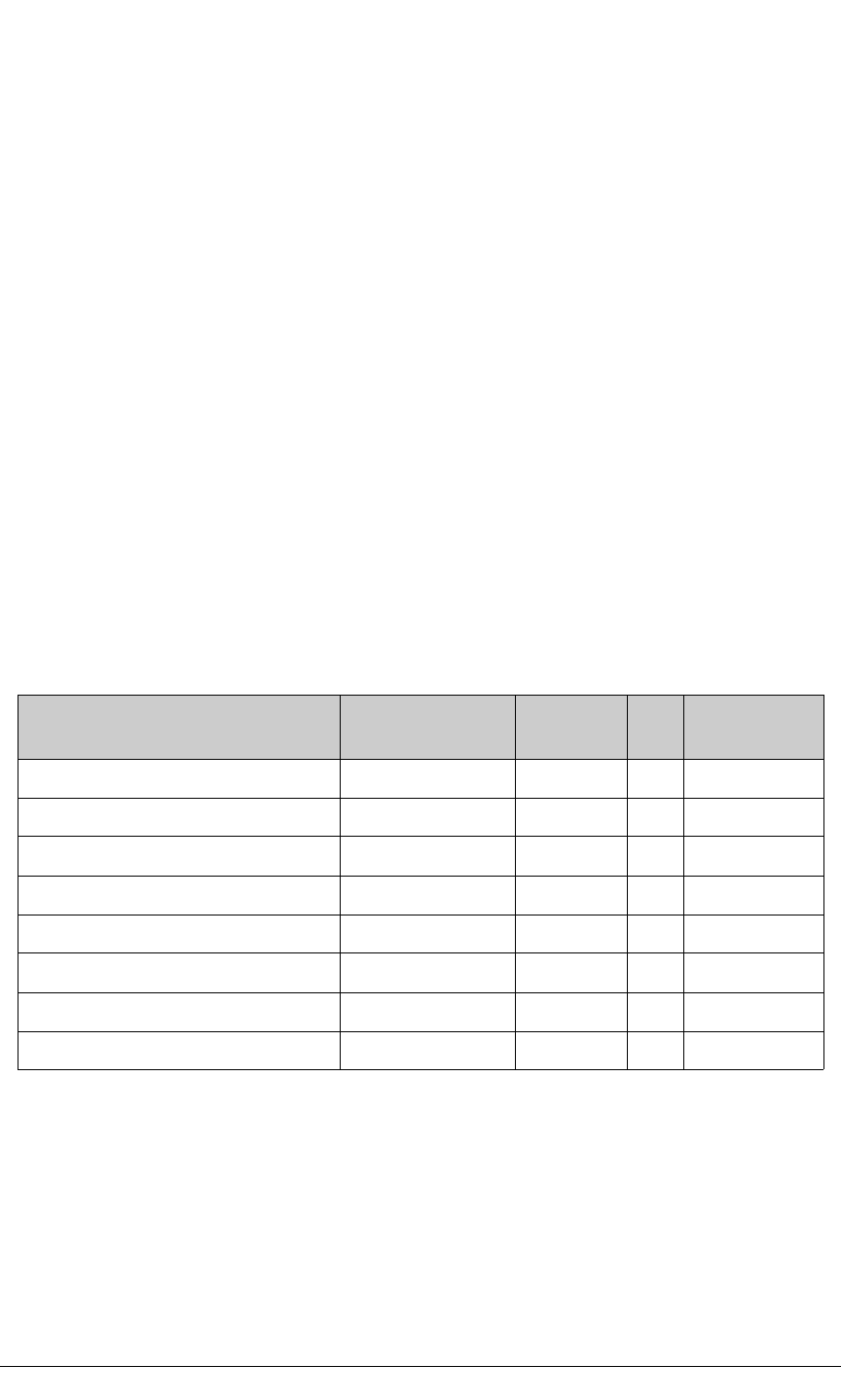
The I/O registers for Timer B are listed in Table 11-6.
Table 11-6. Timer B Registers
Register Name Mnemonic
I/O
address
R/W Reset
Timer B Control/Status Register TBCSR 0xB0 R/W xxxxx000
Timer B Control Register TBCR 0xB1 W xxxx0000
Timer B MSB 1 Register TBM1R 0xB2 W xxxxxxxx
Timer B LSB 1 Register TBL1R 0xB3 W xxxxxxxx
Timer B MSB 2 Register TBM2R 0xB4 W xxxxxxxx
Timer B LSB 2 Register TBL2R 0xB5 W xxxxxxxx
Timer B Count MSB Register TBCMR 0xBE R xxxxxxxx
Timer B Count LSB Register TBCLR 0xBF R xxxxxxxx