


User’s Manual 103
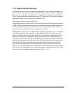
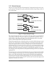
7.12 Pulse Width Modulator
The Pulse Width Modulator consists of a ten-bit free running counter, and four width reg-
isters. Each PWM output is High for "n + 1" counts out of the 1024-clock count cycle,
where "n" is the value held in the width register. The PWM output High time can option-
ally be spread throughout the cycle to reduce ripple on the externally filtered PWM output.
The PWM is clocked by the output of Timer A9.
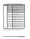
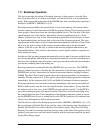
The spreading function is implemented by dividing each 1024-clock cycle into four quad-
rants of 256 clocks each. Within each quadrant, the Pulse Width Modulator uses the eight
MSBs of each pulse-width register to select the base width in each of the quadrants. This
is the equivalent to dividing the contents of the pulse-width register by four and using this
value in each quadrant. To get the exact High time, the Pulse Width Modulator uses the
two LSBs of the pulse-width register to modify the High time in each quadrant according
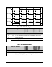
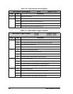
to the table below. The "n/4" term is the base count, formed from the eight MSBs of the
pulse-width register.
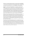
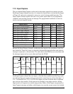
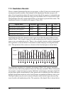
The diagram below shows a PWM output for several different width values, for both
modes of operation. Operation in the spread mode reduces the filtering requirements on
the PWM output in most cases.
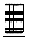
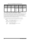
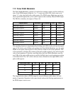
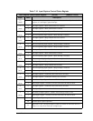
Register Name Mnemonic I/O Address R/W Reset
PWM LSB 0 Register PWL0R 0x88 W xxxxxxxx
PWM MSB 0 Register PWM0R 0x89 W xxxxxxxx
PWM LSB 1 Register PWL1R 0x8A W xxxxxxxx
PWM MSB 1 Register PWM1R 0x8B W xxxxxxxx
PWM LSB 2 Register PWL2R 0x8C W xxxxxxxx
PWM MSB 2 Register PWM2R 0x8D W xxxxxxxx
PWM LSB 3 Register PWL3R 0x8E W xxxxxxxx
PWM MSB 3 Register PWM3R 0x8F W xxxxxxxx
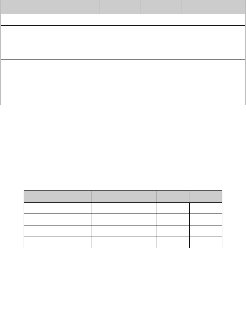
Pulse Width LSBs 1st 2nd 3rd 4th
00 n/4 + 1 n/4 n/4 n/4
01 n/4 + 1 n/4 n/4 + 1 n/4
10 n/4 + 1 n/4 + 1 n/4 + 1 n/4
11 n/4 + 1 n/4 + 1 n/4 + 1 n/4 + 1