


User’s Manual 203
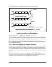
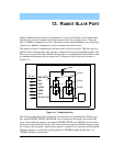
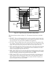
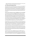
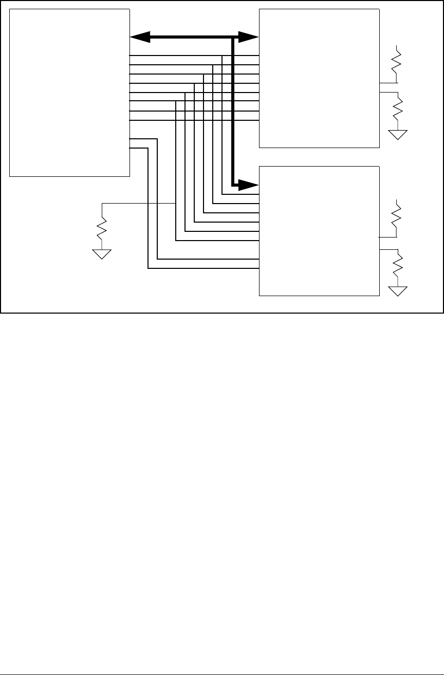
Figure 13-4. Typical Connection Slave Rabbit to Master Rabbit
The slave port lines are shown in Figure 13-1. The function of these lines is described
below.
• SD0–SD7—These are bidirectional data lines, and are generally connected to the data
bus of the master processor. Multiple slaves can be connected to the data bus. The slave
drives the data lines only when /SCS and /SRD are both pulled low.
• SA1, SA0—These are address lines used to select one of the four data registers of the
slave interface. Normally these lines are connected to the low-order address lines of the
master. The master always drives these lines which are always inputs to the slave.
• /SCS—Input. Slave chip select. The slave ignores read or write requests unless the chip
select is low. If a Rabbit is used as a master, this line can be connected to one of the
master’s programmable chip select lines /I0–/I7.
• /SRD—Input. If /SCS is also low, this line pulled low causes the contents of the register
selected by the address lines to be driven on the data bus. If a Rabbit is used as a master,
this line is normally connected to the global I/O read strobe /IORD.
• /SWR—Input. If /SCS is also low, this line causes the data bits on the data bus to be
clocked into the register selected by the address lines on the rising edge of /SWR or
/SCS, whichever rises first. If a Rabbit is used as a master, this line is normally con-
nected to the global I/O write strobe /IOWR.
Master Rabbit
First Slave Rabbit
D0–D7
SD0–SD7
Second Slave Rabbit
/IORD
/IOWR
A0
A1
/SRD
/SWR
SA0
SA1
/SLAVEATTN
INT0A
/RESET
/SCS
/I7
/XTALB1CLK
/I6
/SCS
/SLAVEATTN
INT1A
portout
SMODE0
SMODE1
+
SMODE0
SMODE1
+
Reset
Pulldown