


User’s Manual 137
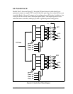
9.5 Parallel Port E
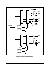
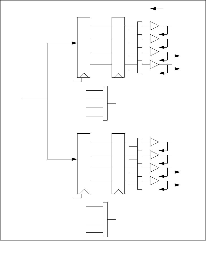
Parallel Port E, shown in Figure 9-2, has eight I/O pins that can be individually pro-
grammed as inputs or outputs. PE7 is used as the slave port chip select when the slave port
is enabled. Each of the port E outputs can be configured as an I/O strobe. In addition, four
of the port E lines can be used as interrupt request inputs. The output registers are cas-
caded and timer-controlled, making it possible to generate precise timing pulses.
Figure 9-2. Parallel Port E Block Diagram
PE7
PE4
I/O Data
perclk/2
Timer A1
Timer B1
Timer B2
perclk/2
Timer A1
Timer B1
Timer B2
PE3
PE0
I6
/scs
Inputs
I4
I7
I5
I2
I0
I3
I1
INT1
INT0
INT1
INT0