


User’s Manual 131
9.2 Parallel Port B
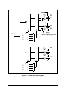
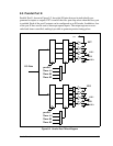
Parallel Port B, has eight pins that can programmed individually to be inputs and outputs.
After reset, Parallel Port B comes up as six inputs (PB[5:0]) and two outputs (PB7 and
PB6). The output value on pins PB6 and PB7 (package pins 99, 100) will be low.
When the auxiliary I/O bus is enabled, Parallel Port B bits 2:7 provide 6 address lines, the
least significant 6 lines of the 16 lines that define the full I/O space.
When the slave port is enabled, parallel port lines PB2–PB7 are assigned to various slave
port functions. However, it is still possible to read PB0–PB5 using the Port B data register
even when lines PB2–PB7 are used for the slave port. It is also possible to read the signal
driving PB6 and PB7 (this signal is on the signaling lines from the slave port logic).
Regardless of whether the slave port is enabled, PB0 reflects the input of the pin unless
Serial Port B has its internal clock enabled, which causes this line to be driven by the serial
port clock. PB1 reflects the input of the pin unless Serial Port A has its internal clock
enabled.
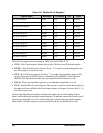
• PBDR—Parallel Port B data register. Read/Write.
• PBDDR—Parallel Port B data direction register. A "1" makes the corresponding pin an
output. This register is write only.
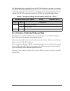
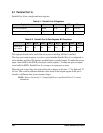
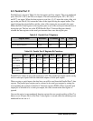
Table 9-3. Parallel Port B Registers
Register Name Mnemonic I/O address R/W Reset
Port B Data Register PBDR 0x40 R/W 00xxxxxx
Port B Data Direction Register PBDDR 0x47 W 11000000
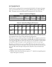
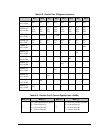
Table 9-4. Parallel Port B Register Bit Functions
Bit 7 Bit 6 Bit 5 Bit 4 Bit 3 Bit 2 Bit 1 Bit 0
PBDR
(R/W)
adr = 0x040
PB7 PB6 PB5 PB4 PB3 PB2 PB1 PB0
PBDDR
(W)
adr = 0x047
dir =
out
dir =
out
dir =
out
dir =
out
dir =
out
dir =
out
dir =
out
dir =
out