


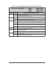
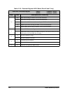
User’s Manual 185
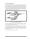
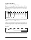
12.7 Clocked Serial Timing
12.7.1 Clocked Serial Timing With Internal Clock
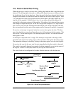
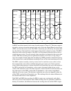
For synchronous serial communication, the serial clock can be either generated by the
Rabbit or by an external device. The timing diagram in Figure 12-6 below can be applied
to both full-duplex and half-duplex clocked serial communication where the serial clock is
generated internally by the Rabbit. Other SPI compatible clock modes supported by the
Rabbit 3000 are shown in Figure 12-5. With an internal clock, the maximum serial clock
rate is perclk/2.
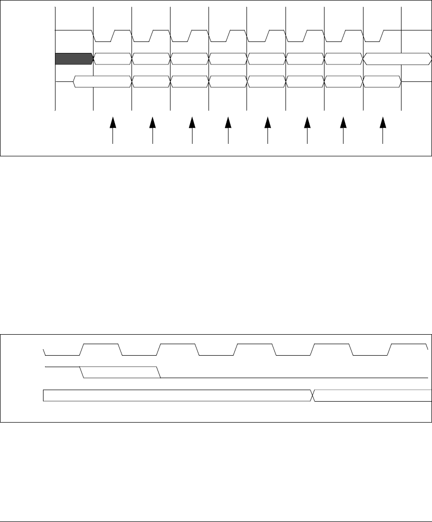
Figure 12-6. Full-Duplex Clocked Serial Timing Diagram with Internal Clock (Mode 00)
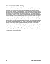
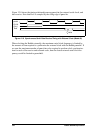
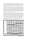
12.7.2 Clocked Serial Timing with External Clock
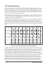
In a system where the Rabbit serial clock is generated by an external device, the clock sig-
nal has to be synchronized with the internal peripheral clock (perclk) before data can be
transmitted or received by the Rabbit. Depending on when the external serial clock is gen-
erated, in relation to perclk, it may take anywhere from 2 to 3 clock cycles for the exter-
nal clock to be synchronized with the internal clock before any data can be transferred.
Figure 12-7 shows the timing relationship among perclk, the external serial clock, and
data transmit.
Figure 12-7. Synchronous Serial Data Transmit Timing with External Clock (Mode 00)
LSB BIT 1 BIT 2 BIT 3 BIT 4 BIT 5 BIT 6
MSB
LSB BIT 1 BIT 2 BIT 3 BIT 4 BIT 5 BIT 6 MSB
23456781
CYCLE
CLKA
TxA
RxA
Rx Capture Strobe
perclk
CLKA
TxA
(ext.)