


User’s Manual 175
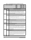
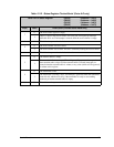
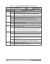
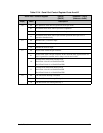
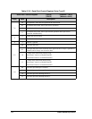
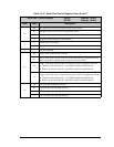
Table 12-16. Serial Port Control Register Ports E and F
Serial Port x Control Register (SECR) (Address = 0xCC)
(SFCR) (Address = 0xDC)
Bit(s) Value Description
7:6
00 No operation. These bits are ignored in the Async mode.
01 In HDLC mode, force receiver in Flag Search mode.
10 No operation.
11 In HDLC mode, transmit an Abort pattern.
5
0 Enable the receiver input.
1 Disable the receiver input.
4 x This bit is ignored.
3:2
00 Async mode with 8 bits per character.
01
Async mode with 7 bits per character. In this mode the most significant bit of a
byte is ignored for transmit, and is always zero in receive data.
10
HDLC mode with external clock. The external clocks are supplied as follows:
• Transmit clock (Serial Port F)—pins PG0 and PG1on Parallel Port G.
• Receive clock (Serial Port E)—pins PG4 and PG5 on Parallel Port G.
11
HDLC mode with internal clock. The clock is 16× the data rate, and the DPLL is
used to recover the receive clock. If necessary, the clocks are supplied as follows:
• Transmit clock (Serial Port F)—pins PG0 and PG1on Parallel Port G.
• Receive clock (Serial Port E)—pins PG4 and PG5 on Parallel Port G.
1:0
00 The serial port interrupt is disabled.
01 The serial port uses Interrupt Priority 1.
10 The serial port uses Interrupt Priority 2.
11 The serial port uses Interrupt Priority 3.