


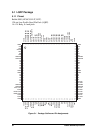
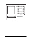
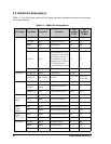
58 Rabbit 3000 Microprocessor
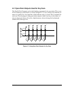
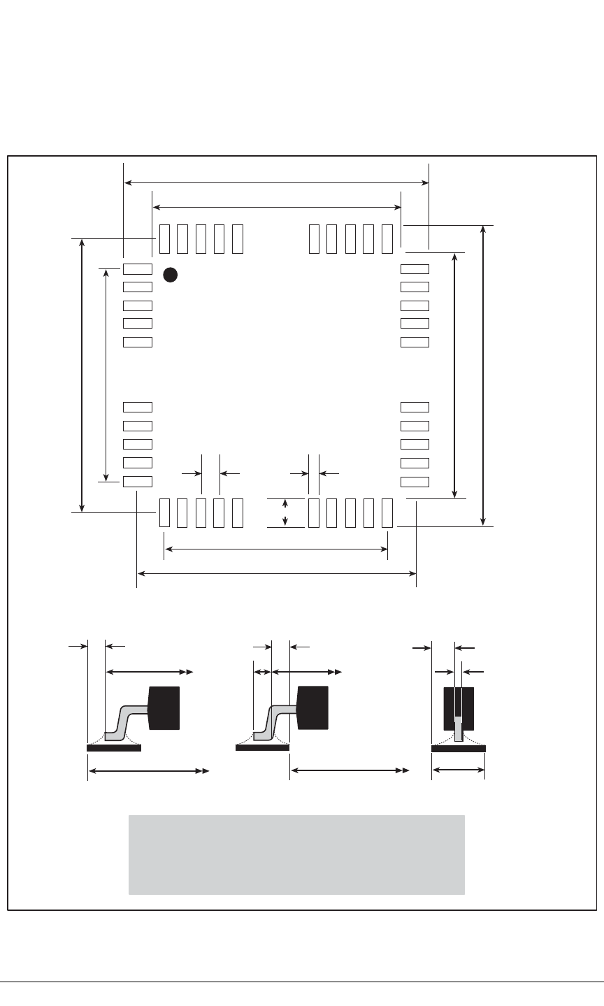
Figure 5-3 shows the PC board land pattern for the Rabbit 3000 chip in a 128-pin LQFP
package. This land pattern is based on the IPC-SM-782 standard developed by the Surface
Mount Land Patterns Committee and specified in Surface Mount Design and Land Pat-
tern Standard, IPC, Northbrook, IL, 1999.
Figure 5-3. PC Board Land Pattern for Rabbit 3000 128-pin LQFP
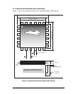
13.75 mm (min.)
16.85 mm (max.)
12.4 mm
15.3 mm
0.28 mm (max.)0.40 mm
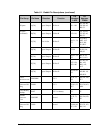
13.75 mm (min.)
16.85 mm (max.)
12.4 mm
15.3 mm
1.55 mm
J
T
: 0.290.55 mm
Toe Fillet
J
H
: 0.290.604 mm
Heel Fillet
J
S
: -0.010.077 mm
Side Fillet
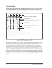
TOLERANCE AND SOLDER JOINT ANALYSIS
Z
max
: 16.85 mm
G
min
: 13.75 mm
X: 0.28 mm
W
min
S
max
L
min
T
Solder fillet min/max (toe, heel, and side respectively)
Toe-to-toe distance across chip
Heel-to-heel distance across chip
Toe-to-heel distance on pin
Width of pin
J:
L:
S:
T:
W:
(max.)