


138 Rabbit 3000 Microprocessor
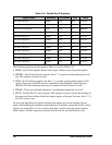
The following registers are described in Table 9-11 and in Table 9-12.
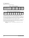
• PEDR—Port E data register. Reads value at pins. Writes to port E preload register.
• PEDDR—Port E data direction register. Set to "1" to make corresponding pin an out-
put. This register is zeroed on reset.
• PEFR—Port E function register. Set bit to "1" to make corresponding output an I/O
strobe. The nature of the I/O strobe is controlled by the I/O bank control registers
(IBxCR). The data direction must be set to output for the I/O strobe to work.
• PEBxR—These are individual registers to set individual output bits on or off.
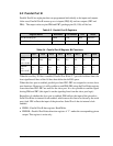
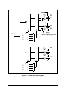
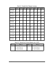
• PECR—Parallel Port E control register. This register is used to control the clocking of
the upper and lower nibble of the final output register of the port. On reset, bits 0, 1, 4,
and 5 are reset to zero.
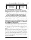
On reset, the data direction register and function register are zeroed, making all pins
inputs, and disabling the alternate output functions. In addition certain bits in the control
register are zeroed (bits 0,1,4,5) to ensure that data is clocked into the output registers
when loaded. All other registers associated with Port E are not initialized on reset.
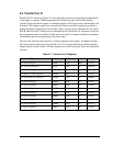
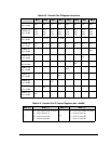
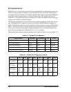
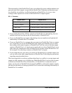
Table 9-10. Parallel Port E Registers
Register Name Mnemonic I/O address R/W Reset
Port E Data Register PEDR 0x70 R/W xxxxxxxx
Port E Control Register PECR 0x74 W xx00xx00
Port E Function Register PEFR 0x75 W 00000000
Port E Data Direction Register PEDDR 0x77 W 00000000
Port E Bit 0 Register PEB0R 0x78 W xxxxxxxx
Port E Bit 1 Register PEB1R 0x79 W xxxxxxxx
Port E Bit 2 Register PEB2R 0x7A W xxxxxxxx
Port E Bit 3 Register PEB3R 0x7B W xxxxxxxx
Port E Bit 4 Register PEB4R 0x7C W xxxxxxxx
Port E Bit 5 Register PEB5R 0x7D W xxxxxxxx
Port E Bit 6 Register PEB6R 0x7E W xxxxxxxx
Port E Bit 7 Register PEB7R 0x7F W xxxxxxxx