


118 Rabbit 3000 Microprocessor
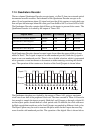
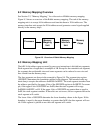
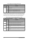
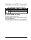
Figure 8-4. Memory Segments
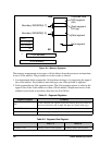
The memory management unit accepts a 16-bit address from the processor and translates
it into a 20-bit address. The procedure to do this works as follows.
1. It is determined which segment the 16-bit address belongs to by inspecting the upper 4
bits of the address. Every address must belong to one of the possible 4 segments.
2. Each segment has an 8-bit segment register. The 8-bit segment register is added to the
upper 4 bits of the 16-bit address to create a 20-bit address. Wraparound occurs if the
addition would result in an address that does not fit in 20 bits.
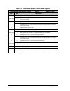
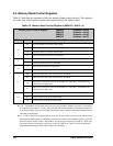
Table 8-1. Segment Registers
Segment Register Function
XPC
Locates extended code segment in physical memory. Read and written by
processor instructions: ld a,xpc, ld xpc,a, lcall, lret, ljp
STACKSEG = 0x11 Locates stack segment in physical memory.
DATASEG = 0x12 Locates data segment in physical memory.
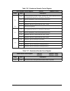
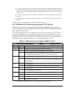
Table 8-2. Segment Size Register
Bits 7..4 Bits 3..0
SEGSIZE = 0x13 Boundary address stack segment. Boundary address data segment.
Extended code
XPC segment
(8K)
Stack segment
(4K typ)
Root segment
Data segment
64K
0K
Boundary SEGSIZE[4..7]
Boundary SEGSIZE[0..3]
XPC
STACKSEG
DATASEG
00
+
16-bit address
20-bit address