


312 Rabbit 3000 Microprocessor
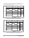
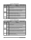
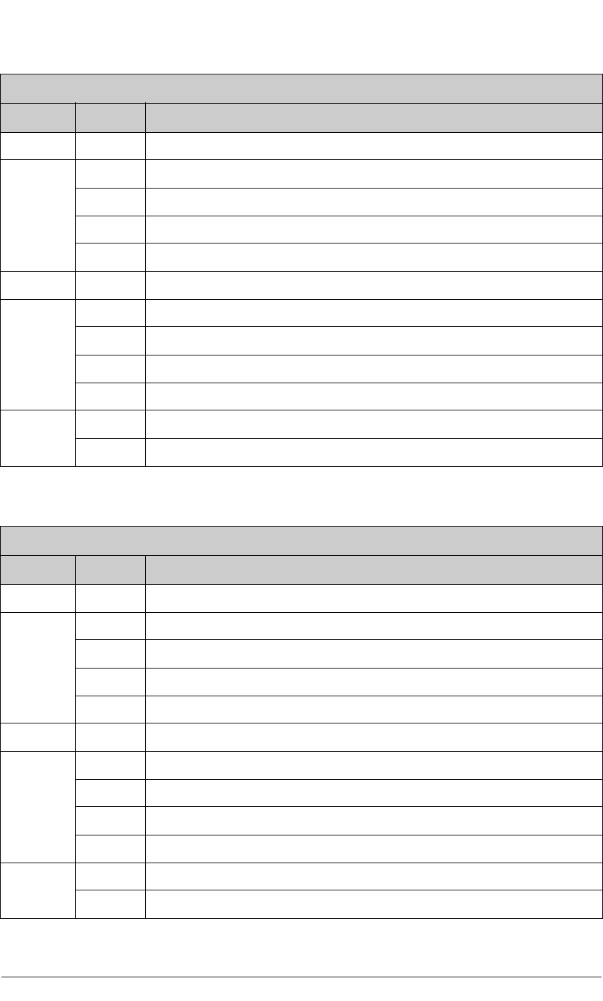
Table B-25. PWM LSB 0 Register
PWM LSB 0 Register (PWL0R) (Address = 0x0088)
Bit(s) Value Description
7:6 write The least significant two bits for the Pulse Width Modulator count are stored.
5:4 00 Normal PWM operation.
01 Suppress PWM output seven out of eight iterations of PWM counter.
10 Suppress PWM output three out of four iterations of PWM counter.
11 Suppress PWM output one out of two iterations of PWM counter.
3 This bit is ignored and should be written with zero.
2:1 00 Pulse Width Modulator interrupts are disabled.
01 Pulse Width Modulator interrupts use Interrupt Priority 1.
10 Pulse Width Modulator interrupts use Interrupt Priority 2.
11 Pulse Width Modulator interrupts use Interrupt Priority 3.
0
0 PWM output High for single block.
1 Spread PWM output throughout the cycle.
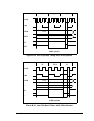
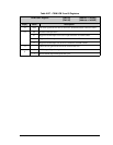
Table B-26. PWM LSB 1 Register
PWM LSB 1 Register (PWL1R) (Address = 0x008A)
Bit(s) Value Description
7:6 write The least significant two bits for the Pulse Width Modulator count are stored.
5:4 00 Normal PWM operation.
01 Suppress PWM output seven out of eight iterations of PWM counter.
10 Suppress PWM output three out of four iterations of PWM counter.
11 Suppress PWM output one out of two iterations of PWM counter.
3 This bit is ignored and should be written with zero.
2:1 00 Normal PWM interrupt operation.
01 Suppress PWM interrupts seven out of eight iterations of PWM counter.
10 Suppress PWM interrupts three out of four iterations of PWM counter.
11 Suppress PWM interrupts one out of two iterations of PWM counter.
0
0 PWM output High for single block.
1 Spread PWM output throughout the cycle.