


User’s Manual 173
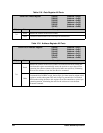
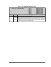
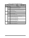
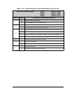
Table 12-14. Serial Port Control Register Ports A and B
Serial Port x Control Register (SACR) (Address = 0xC4)
(SBCR) (Address = 0xD4)
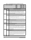
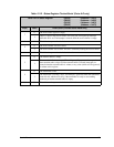
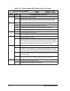
Bit(s) Value Description
7:6 00 No operation. These bits are ignored in the Async mode.
01 In clocked serial mode, start a byte receive operation.
10 In clocked serial mode, start a byte transmit operation.
11
In clocked serial mode, start a byte transmit operation and a byte receive
operation simultaneously.
5:4 00 Parallel Port C is used for input.
01 Parallel Port D is used for input.
1x Disable the receiver input.
3:2 00 Async mode with 8 bits per character.
01
Async mode with 7 bits per character. In this mode the most significant bit of a
byte is ignored for transmit, and is always zero in receive data.
10
Clocked serial mode with external clock.
Serial Port A clock is on Parallel Port PB1
Serial Port B clock is on Parallel Port PB0
11
Clocked serial mode with internal clock.
Serial Port A clock is on Parallel Port PB1
Serial Port B clock is on Parallel Port PB0
1:0 00 The Serial Port interrupt is disabled.
01 The Serial Port uses Interrupt Priority 1.
10 The Serial Port uses Interrupt Priority 2.