Integrating GSP-1620 Modems into OEM Products
80-99208-1 Rev. D 7-11
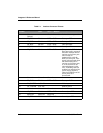
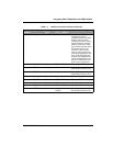
15 CP_DSR RS-232 DTE <- DCE This pin is the DSR for the
Control port and is
asserted when the modem
detects activity on the
Control port and is ready
to communicate with the
DTE over this port. This
signal is de-asserted when
the modem detects no
activity on the Control
port; or is de-asserted as
an acknowledgment to the
user, indicating that the
modem has completed its
power- down sequence as
no active DTR lines were
seen on the serial ports.
16 CP_RXD RS-232 DTE <- DCE Control port RXD
17 MIC_P Analog Input to modem Analog Microphone Input
(Reserved for Future Use)
18 MIC_N Analog Input to modem Analog Microphone Input
(Reserved for Future Use)
19 Reserved Reserved Reserved
20 DP_DTR RS-232 DTE -> DCE Data port DTR
21 Ground Ground Ground return Ground return
22 DP_RI RS-232 DTE <- DCE Data Port RI
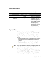
23 SPKR_P Analog Output from
modem
Analog speaker output
(Reserved for Future Use)
Table 7-1. Interface Connector Pinouts (continued)
Pin
Number
Signal Name Signal
Level
Direction
User <-> Modem
Description


