Quick Bench Set-Up
80-99208-1 Rev. D 2-7
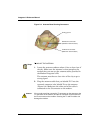
Connecting the Diagnostic Cable
The Diagnostic cable lets you:
• Service-program GSP-1620 modems, using the
Globalstar User Terminal Program Support Tool
(UTPST). For more information about the UTPST, see
UTPST Overview on page 3-2.
• Monitor or verify some modem functions, using the
QUALCOMM Globalstar Modem Operation Monitor.
For more information, see the QUALCOMM Globalstar
Modem Operation Monitor User’s Guide, 80-99399-1.
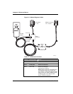
The cable includes an optional AC adapter. If a DC power
supply is not available on your bench, you can power the
modem with the AC adapter on the Diagnostic cable.
The Diagnostic cable also includes a switch box that controls
whether the cable’s DTR (Data Terminal Ready) signal is
asserted (“POS 1 DTR to GND”) or de-asserted (“POS 2 DTR
Open” or “POS 3 Not Used”). When DTR is asserted, the
modem powers up immediately if power is provided. Before
powering down the modem with this cable attached, you must
set this switch to “POS 2” or “POS 3.”
Note
On the switch box, “POS 2 DTR Open” and “POS 3 Not Used” are
functionally equivalent. Some cables are equipped with a two-position
switch box and do not have “POS 3.” The switch positions for these
cables are “POS 1 DTR to GND” (DTR asserted) and “POS 2 DTR
Open” (DTR de-asserted).
Tip
When the Diagnostic cable is connected but you are not using the
UTPST to service-program the modem, leave the Diagnostic cable
switch in the “POS 2 DTR Open” (de-asserted) position.


