Integrator’s Reference Manual
2-2 80-99208-1 Rev. D
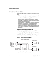
Connecting Hardware Components
The setup process for the GSP-1620 modem includes:
• A quick tour of the modem
• Connecting the modem cables
❑ Connecting the Interface cable (Data port, Control
port, power) to the modem and to your PC
❑ Connecting the antenna cables (Tx, Rx) to the modem
❑ Connecting the Diagnostic cable (if you want to power
the modem from its AC adapter, service-program the
modem, or monitor some modem functions)
• Connecting and mounting the antenna
• Mounting the modem (optional)
• Grounding the system
• Providing power to the modem
• Setting up HyperTerminal to talk to the modem and
testing your connection
Tip
A Windows PC is recommended for modem bench setup and
application development. Modems must be service programmed using
the Globalstar UT Program Support Tool, which is a Windows software
application.
A Quick Tour of the Modem
For quick bench set-up, first remove the GSP-1620 modem
from the GSP-1620 Modem Integrator’s Kit.
Caution
When handling the modem, observe precautions necessary to avoid
damage by electrostatic discharge (ESD).
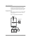
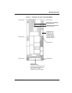
Compare the GSP-1620 modem to Figure 2-1. This
illustration shows the connectors and components you will
use in the following sections.


