Developing Modem Applications
80-99208-1 Rev. D 5-7
Working with Modem Features
This section discusses key features of the GSP-1620 modem
and how to use them programmatically in your application.
The features discussed in this section work with either packet
data or asynchronous data. For packet-specific features, see
Using Packet Data on page 5-21. For asynchronous-specific
features, see Using Asynchronous Data on page 5-30.
Using Data and Control Ports
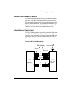
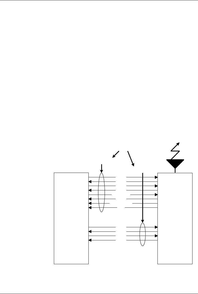
The GSP-1620 modem has two serial ports: one for Data and
one for Control. The Data and Control ports make up the Rm
interface, which is the serial interface between the DTE (your
application) and the DCE (GSP-1620 modem), as shown in
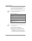
Figure 5-2.
Figure 5-2. DTE-to-DCE Rm Interface
DTE
(SCADA
Application)
DCE
(GSP-1620
Modem)
Data Port
Um Interface
Control Port
Rm Interface
TxD
RxD
DTR
DSR
RLSD (DCD)
CTS
RI
RFR (RTS)
TxD
RxD
DTR
DSR


