Quick Bench Set-Up
80-99208-1 Rev. D 2-9
1
2
3
Steps
TO CONNECT THE DIAGNOSTIC PORT CABLE
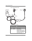
1. Connect the DE-9 modem connector (“P2-Module”) on the
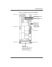
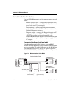
Diagnostic cable (Figure 2-3) to the 9-pin Diagnostic port
on the modem (Figure 2-1).
2. Connect the DE-9 PC connector (“P1-PC”) on the
Diagnostic cable to a COM port on your computer.
3. Locate the switch on the cable, and set it to “POS 1 DTR
to GND.”
Do not plug in the AC wall adapter yet. For information
about powering the modem, see Providing Power to the
Modem on page 2-12.
Connecting and Mounting the Antenna
The GSP-1620 modem uses a Dielectric Resonator Antenna
(DRA) with a passive transmit and an active receive section.
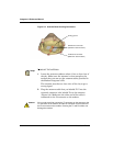
The transmit (Tx) and receive (Rx) connectors are labeled on
the base of the antenna.
Since the antenna communicates with Globalstar satellites, it
must be positioned outdoors where it has a clear view of the
sky, unimpeded by tall obstacles such as buildings and trees.
Caution
Antenna cable length is limited, due to insertion loss and potential
emission problems. For details, see Antenna Cable Specifications on
page 7-25 and Calculating Antenna Cable Length on page 7-27.
Tip
For a quick setup, you may want to mount the antenna on top of a
water-tight box on your roof. Mount the modem inside the box, then run
extension cables (straight RS-232 9-pin serial cables with no
crossovers) for the power and serial connectors to your indoor bench.
(For maximum RS-232 extension cable lengths, see the TIA/EIA-232-E
specification.) A box setup lets you use the antenna cables from the kit,
without worrying about antenna cable length.


