Integrator’s Reference Manual
2-8 80-99208-1 Rev. D
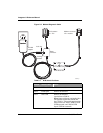
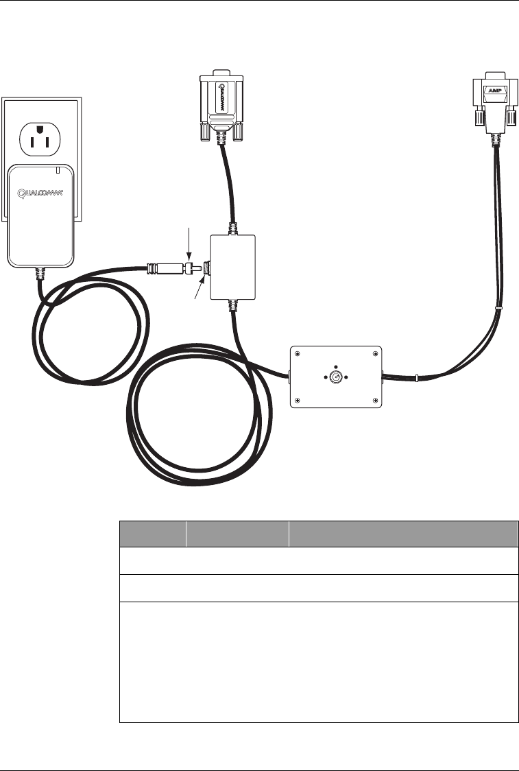
Figure 2-3. Modem Diagnostic Cable
POS 1
DTR to GRD
POS 2
DTR OPEN
POS 3
NOT USED
PC Connector
"P1 - PC"
Modem connector
"P2 - module"
Lock ring
AC Wall
adapter
Locking
threads
Power
connector
DTR Switch box
005AA_01
Table 2-1. DTR Switch Positions
Position Switch Label Effect
POS 1 DTR to GND DTR is asserted.
POS 2 DTR Open DTR is de-asserted.
POS 3 Not Used DTR is de-asserted
(equivalent to POS 2).
Note: Some cables are equipped with a
two-position switch box and do not
have “POS 3.” The switch positions for
these cables are “POS 1 DTR to GND”
(DTR asserted) and “POS 2 DTR
Open” (DTR de-asserted).


