Integrator’s Reference Manual
7-14 80-99208-1 Rev. D
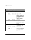
Table 7-2. Diagnostic Port Pinouts
Pin
Number
Signal Name Direction
User <-> Modem
Description
1 Ground Ground return Ground return
2DM_RXDOutput from
modem
Diagnostic port RXD
3 DM_TXD Input to modem Diagnostic port TXD
4 DM_DTR_N Input to modem Diagnostic port DTR
The DTR line has only one function:
to turn on the modem when power is
applied but no other device is
connected. When DTR is asserted, the
modem powers up immediately if
power is provided.
Pulled high to input voltage through
a 47K resistor in the modem.
5 Ground Ground return Ground return
6 Input DC POWER Input/Output Used for an active translator
Diagnostic cable. 5.6V-16V,
unfiltered in the modem. If this pin is
used as the source of power to the
modem, users must provide sufficient
filtering to comply with conducted
EMI specifications; see DC Power on
page 7-15.
7 DM_RTS_N Input to modem Diagnostic port RTS
Used for hardware flow control.
8DM_CTS_NOutput from
modem
Diagnostic port CTS
Used for hardware flow control.
9 DM_PROGRAM_
FLASH
Allows programming of the modem.
Apply 13V +/- 10%, 50mA (maximum)
to program the flash in the modem.
This is required for all software
upgrades as well as service
programming.


