


99-00984-20-B0
29 | CHAPTER 4 – INTEGRATING OTHER DEVICES WITH YOUR INTERACTIVE
WHITEBOARD SYSTEM
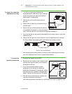
7. Reattach and tighten the four screws on either side of the cable covers you
removed in step 2 of the procedure on page 26.
8. Reposition the input/output cover by sliding it towards the projector.
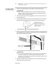
To reattach your
interactive whiteboard
1. With the help of another person, hang your interactive whiteboard on the two
wall-mounting brackets.
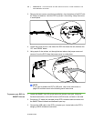
2. Secure the L-shaped metal brackets to the wall
anchors with the screws you removed in step 4
of the procedure on page 27.
NOTE
If you want to lock your interactive
whiteboard with a security cable, see To
lock the pen tray to the interactive
whiteboard on page 47 before securing
these brackets.
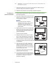
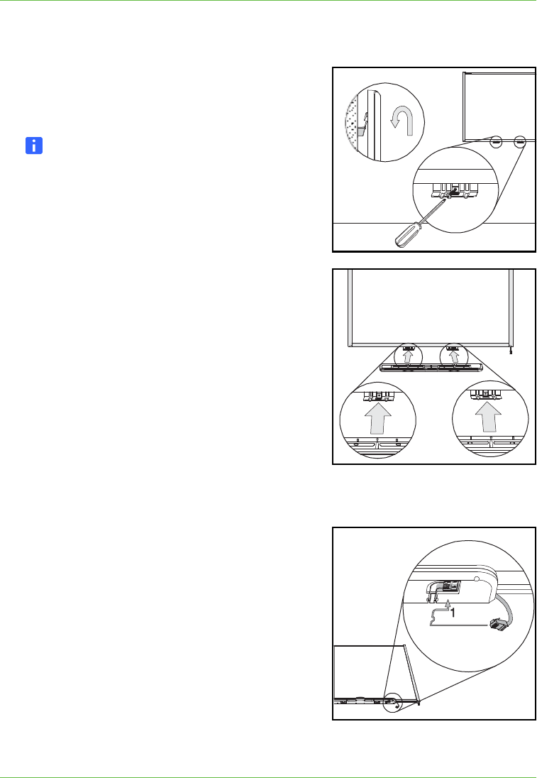
3. Align the pen tray with the two L-shaped metal
brackets, and then slide it toward the wall until it
rests snugly against the bottom frame of your
interactive whiteboard.
The pen tray clicks into place.
4. Optionally, attach security screws to the pen
tray. For more information see To secure the
pen tray to the pen tray brackets on page 48.
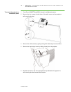
5. Route the modular I²C cable through the cable
management channel under the lower-right end of the pen tray, and then connect
it to receptacle 1.
6. Press the cable into the cable management
channel on the bottom of the tray. This step
protects the modular cable’s RJ11 connector
from damage if the pen tray is removed without
first disconnecting the cable.
7. Place the four pens and the eraser into their
respective slots in the pen tray.
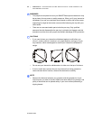
8. In the unlikely event that the image alignment
has been altered, adjust the image according to
the procedure in Aligning the Image After
Installation on page 42.