


44 | CHAPTER 5 – MAINTAINING AND TROUBLESHOOTING YOUR SMART BOARD
685ix INTERACTIVE WHITEBOARD SYSTEM
99-00984-20-B0
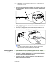
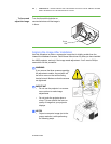
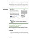
WARNING
When adjusting the projector’s image, only loosen the locking screw next to
the lock and unlock symbols (see the gray screw in the previous illustration).
Never loosen other locking screws or loosen the center nut attached to the
projector bolt as your projector might fall.
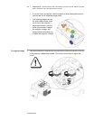
2. Turn the two locking collars, the ridged chrome screws under the blue and green
knobs, in two complete counter-clockwise turns to adjust the knobs.
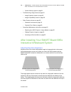
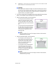
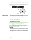
3. Adjust the projected image’s horizontal keystoning.
– Turn the purple knob clockwise if the left
edge of the projected image is shorter
than the right edge and the sides of the
projected image slope inward toward the
left.
– Turn the purple knob counterclockwise if
the right edge of the projected image is
shorter than the left edge and the sides
of the projected image slope inward
toward the right.
NOTE
Ignore the position of the rest of the image in relation to the interactive
whiteboard during this step.
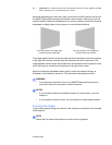
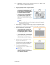
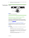
4. Adjust the projected image’s vertical keystoning.
– Turn the green knob clockwise if the
bottom edge of the projected image is
narrower than the top edge, and the
sides of the projected image slope
inward toward the bottom.
– Turn the green knob counterclockwise
if the bottom edge of the projected
image is wider than the top edge, and
the sides of the projected image slope
outwards toward the bottom.
NOTE
Ignore the position of the rest of the image in relation to the interactive
whiteboard during this step.