


112 CHAPTER 15: ROUTING CONFIGURATION GUIDE
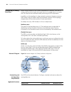
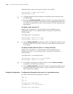
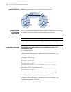
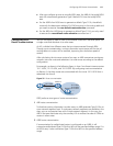
Network Diagram Figure 31 Network diagram for (totally) NSSA area configuration
Networking and
Configuration
Requirements
Run OSPF on the network devices. Based on actual conditions, you can configure
an (totally) NSSA area to reduce the routing table size in the area.
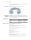
Applicable Products
Configuration Procedure Non-backbone area and backbone area configuration (area 1 is a
non-backbone area)
■ Configure Switch A.
# Create VLANs and configure IP addresses for the VLAN interfaces. The
configuration procedure is omitted.
# Configure OSPF for area 1.
<SwitchA> system-view
[SwitchA] ospf 1 router-id 1.1.1.1
[SwitchA-ospf-1] area 1
[SwitchA-ospf-1-area-0.0.0.1] network 10.2.1.0 0.0.0.255
# Configure OSPF for the backbone area.
[SwitchA-ospf-1] area 0
[SwitchA-ospf-1-area-0.0.0.0] network 10.1.1.0 0.0.0.255
■ Configure Switch B (refer to “Configure Switch A.” on page 112).
■ Configure Switch C.
# Create VLANs and configure IP addresses for the VLAN interfaces. The
configuration procedure is omitted.
# Configure a static route of 2.0.0.0/8.
Area 0
Area 1
NSSA
Area 2
Switch C
Vlan-int100
10.1.1.2/24
Vlan-int100
10.1.1.1/24
Vlan-int300
10.4.1.1/24
Vlan-int200
10.2 .1.2/24
Switch B
Vlan-int200
10.3.1.1/24
Vlan-int200
10.3.1.2/24
Switch A
Vlan-int200
10.2.1.1/24
Vlan-int300
10.5.1.1/24
Switch D
ASBR
ASBR
Product series Software version Hardware version
Switch 5500 Release V03.02.04 All versions
Switch 5500G Release V03.02.04 All versions
Switch 4500 Release V03.03.00 All versions