


200 CHAPTER 21: DHCP CONFIGURATION GUIDE
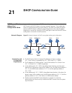
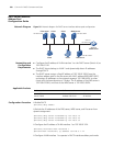
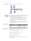
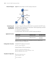
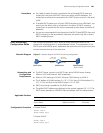
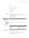
Network Diagram Figure 55 Network diagram for DHCP relay agent configuration
Networking and
Configuration
Requirements
■ VLAN-interface 1 on the DHCP relay agent (Switch A) connects to the network
where DHCP clients reside. The IP address of VLAN-interface 1 is 10.10.1.1/24
and the IP address of VLAN-interface 2 is 10.1.1.2/24.
■ The clients (except Host A, which uses a fixed IP address of 10.10.10.5/24)
dynamically obtain IP addresses from the DHCP server at 10.1.1.1/24.
■ Switch A forwards messages between DHCP clients and the DHCP server to
assign IP addresses in subnet 10.10.1.0/24 and related configuration
information to the clients.
■ Enable the address check function on Switch A to allow only the clients with
valid fixed IP addresses or with IP addresses obtained from the DHCP server to
access external networks.
Applicable Products
Configuration Procedure # Create DHCP server group 1 and specify DHCP server 10.1.1.1 for it.
[SwitchA] dhcp-server 1 ip 10.1.1.1
# Configure the IP address of VLAN-interface 1 as 10.10.1.1/24.
[SwitchA] interface Vlan-interface 1
[SwitchA-Vlan-interface1] ip address 10.10.1.1 24
# Map VLAN-interface 1 to DHCP server group 1.
[SwitchA-Vlan-interface1] dhcp-server 1
[SwitchA-Vlan-interface1] quit
# Bind the IP address 10.10.10.5/24 to the MAC address 0001-0010-0001 of Host
A on the DHCP relay agent.
Switch B
DHCP server
Switch A
DHCP relay
Host A
IP:10.10.10.5/24
MAC:0001-0010-0001
DHCP client
DHCP clientDHCP client
Vlan-int2
10.1.1.2 /24
Vlan-int1
10.10.1.1/24
Vlan-int2
10.1.1.1 /24
Product series Software version Hardware version
Switch 5500 Release V03.02.04 All versions
Switch 5500G Release V03.02.04 All versions
Switch 4500 Release V03.03.00 All versions