


84 CHAPTER 14: MSTP CONFIGURATION GUIDE
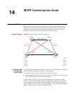
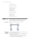
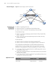
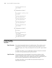
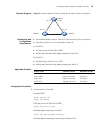
Network Diagram Figure 24 Network diagram for RSTP configuration
Networking and
Configuration
Requirements
■ Switch A is operating at the core.
■ Switch B and Switch C are operating at the distribution layer.
■ Switch D, Switch E, and Switch F are operating at the access layer.
At the distribution layer:
■ Switch C is operating as the backup switch of Switch B. When Switch B fails,
Switch C takes over.
■ Switch C and Switch B are connected through two links. When a link fails,
another link takes over.
At the access layer:
■ Switch D, Switch E, and Switch F are directly connected to PCs.
■ Switch D, Switch E, and Switch F are connected to Switch C and Switch B.
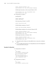
In the configuration procedure below, only RSTP-related configurations are
provided. Switch A is the root bridge. Switch D through Switch F are mostly
consistent in the configuration, so only the configuration on Switch D is listed.
n
■ In most cases, Switch A is a high-end switch or middle-range switch, such as
Switch 8800 or Switch 7750.
■ In most cases, Switch B and Switch C are stackable switches such as the Switch
5500 and Switch 5500G.
■ In most cases, Switch D, Switch E, and Switch F are stackable switches such as
the Switch 4210 and the Switch 4200G.
Applicable Products
Switch F
Switch A
Switch E
Switch D
Switch CSwitch B
Eth 1/0/1
GE 2/0/1 GE 2/0/2
Eth 1/0/4
Eth 1/0/2
Eth 1/0/6
Eth 1/0/5
Eth 1/0/5
Eth 1/0/6
Eth 1/0/1
Eth 1/0/2
Eth 1/0/3
Eth 1/0/1
Eth 1/0/2
Eth 1/0/1
Eth 1/0/2
Eth 1/0/2
Eth 1/0/1
Eth 1/0/3 Eth 1/0/4
Product series Software version Hardware version
Switch 5500 Release V03.02.04 All versions
Switch 5500G Release V03.02.04 All versions