


Configuring Anycast RP Application 163
After the peering relationship is established, the multicast receiver can receive
multicast data from the source.
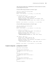
# View the PIM routing information on Switch C again.
[Switch C] display pim routing-table
PIM-SM Routing Table
Total 1 (S,G) entries, 0 (*,G) entry, 0 (*,*,RP) entry
(10.110.5.100, 225.1.1.1)
Protocol 0x20: PIMSM, Flag 0x80004: SPT
Uptime: 00:00:55, Timeout in 208 sec
Upstream interface: Vlan-interface1, RPF neighbor: NULL
Downstream interface list:
Vlan-interface2, Protocol 0x200: SPT, timeout in 200 sec
Matched 1 (S,G) entries, 0 (*,G) entry, 0 (*,*,RP) entry
# View the PIM routing information on Switch F again.
[SwitchF] display pim routing-table
PIM-SM Routing Table
Total 1 (S,G) entry, 3 (*,G) entries, 0 (*,*,RP) entry
(*, 224.1.1.1), RP 10.1.1.1
Protocol 0x20: PIMSM, Flag 0x2003: RPT WC NULL_IIF
Uptime: 00:25:26, never timeout
Upstream interface: Null, RPF neighbor: 0.0.0.0
Downstream interface list:
Vlan-interface2, Protocol 0x1: IGMP, never timeout
(192.168.3.1, 224.1.1.1)
Protocol 0x20: PIMSM, Flag 0x4: SPT
Uptime: 00:02:56, Timeout in 202 sec
Upstream interface: Vlan-interface1, RPF neighbor: 192.168.1.1
Downstream interface list:
Vlan-interface2, Protocol 0x1: IGMP, never timeout
Matched 1 (S,G) entry, 3 (*,G) entries, 0 (*,*,RP) entry
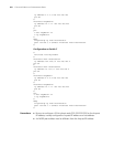
Complete Configuration Configuration on Switch C
#
multicast routing-enable
#
interface Vlan-interface100
ip address 10.110.1.1 255.255.255.0.
pim sm
#
interface Vlan-interface101
ip address 192.168.1.1 255.255.255.0
pim sm
#
interface Vlan-interface103
ip address 10.110.1.1 255.255.255.0
pim sm
#
interface LoopBack1