


22
ACL CONFIGURATION GUIDE
Configuring Basic
ACLs
Basic ACLs filter packets based on only source IP address.
The numbers of basic ACLs range from 2000 to 2999.
Network Diagram
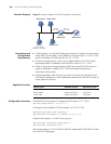
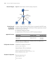
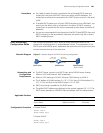
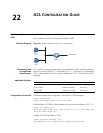
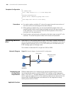
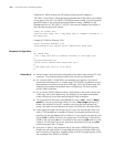
Figure 58 Network diagram for basic ACL configuration
Networking and
Configuration
Requirements
PC 1 and PC 2 connect to the switch through Ethernet 1/0/1 (assuming that the
switch is a Switch 5500). PC 1’s IP address is 10.1.1.1. Apply an ACL on Ethernet
1/0/1 to deny packets with the source IP address of 10.1.1.1 from 8:00 to 18:00
everyday.
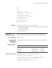
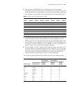
Applicable Products
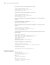
Configuration Procedure # Define a periodic time range that is from 8:00 to 18:00 everyday.
<3Com> system-view
[3Com] time-range test 8:00 to 18:00 daily
# Define basic ACL 2000 to filter packets with the source IP address of 10.1.1.1.
[3Com] acl number 2000
[3Com-acl-basic-2000] rule 1 deny source 10.1.1.1 0 time-range test
[3Com-acl-basic-2000] quit
# Apply ACL 2000 to Ethernet 1/0/1.
[3Com] interface Ethernet 1/0/1
[3Com-Ethernet1/0/1] packet-filter inbound ip-group 2000
Switch
Eth1/0/1
PC 1
10.1.1.1
PC 2
To the router
Product series Software version Hardware version
Switch 5500 Release V03.02.04 All versions
Switch 5500G Release V03.02.04 All versions
Switch 4500 Release V03.03.00 All versions