


80 CHAPTER 14: MSTP CONFIGURATION GUIDE
instance 4 vlan 40
active region-configuration
#
■ Configuration on Switch C
#
stp instance 4 root primary
stp region-configuration
region-name example
instance 1 vlan 10
instance 3 vlan 30
instance 4 vlan 40
active region-configuration
#
■ Configuration on Switch D
#
stp region-configuration
instance 1 vlan 10
instance 3 vlan 30
instance 4 vlan 40
active region-configuration
#
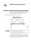
Configuring
VLAN-VPN Tunneling
VLAN-VPN tunneling enables BPDUs to be transparently transmitted between
geographically dispersed customer networks through a specific VLAN VPN over
the service provider network. This allows the customer networks to share a
spanning tree independent of that of the service provider network.
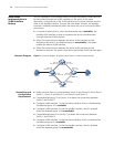
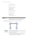
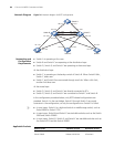
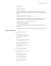
Network Diagram
Figure 23 Network diagram for VLAN-VPN tunneling configuration
Networking and
Configuration
Requirements
■ Use the Switch 5500 (Switch C and Switch D in the network diagram) as access
devices of the service provider network.
■ Use the Switch 4210 (Switch A and Switch B in the network diagram) as access
devices of the customer networks.
■ Connect Switch C and Switch D through trunk ports. Enable VLAN-VPN
tunneling in system view to achieve transparent transmission between the
customer networks over the service provider network.
Eth 1/0/1
Switch A
Switch D
Switch C
Switch B
Eth 1/0/1
Eth 1/0/2
Eth 1/0/1
Eth 1/0/2
Eth 1/0/1