


VRRP Interface Tracking 189
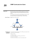
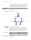
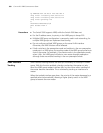
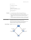
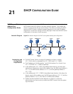
Network Diagram Figure 51 Network diagram for VRRP
Networking and
Configuration
Requirements
Switch A is the master and Switch B is the backup in a VRRP group. Both Switch A
and Switch B have an interface connected with the Internet. Configure the VRRP
interface tracking function, so that when the interface connected with the
Internet on Switch A becomes unavailable, Switch B can replace Switch A to act as
the gateway even if Switch A is still working.
Set the group number to 1.
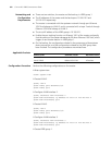
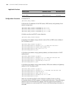
Applicable Products
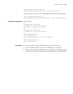
Configuration Procedure
■ Configure Switch A.
# Configure VLAN 2.
<LSW-A> system-view
[LSW-A] vlan 2
[LSW-A-vlan2] port Ethernet1/0/6
[LSW-A-vlan2] quit
[LSW-A] interface Vlan-interface 2
[LSW-A-Vlan-interface2] ip address 202.38.160.1 255.255.255.0
[LSW-A-Vlan-interface2] quit
# Enable the VRRP group to respond to ping operations destined for its virtual IP
address.
[LSW-A] vrrp ping-enable
LSW A
Host B
LSW B
Vlan-int3
10.100.10.2/24
Vlan-int2
202.38.160.1/24
Vlan-int2
202.38.160.2/24
202.38.160.3/24
10.2.3.1/24
Host A
Internet
Virtual IP address
2
02.38.160.111/24
Product series Software version Hardware version
Switch 5500 Release V03.02.04 All versions
Switch 5500G Release V03.02.04 All versions